General
1.1 Pre-plan the works to consider the many aspects of works that need to be installed CLEAR of framing and be supported BY the framing. Once sheeted, it’s a mess to be cutting holes in the linings to remove/move/provide more framing!
1.2 One of the most common issues is framing (or substrate in the case of direct stick) that is out of tolerance, in the wrong location, built to a set-out that does not provide the correct lining support or accommodate other building elements.
1.3 Framing (or substrate for direct stick) needs to be plumb, square straight and in the correct set-out (including a joint layout location and detail) location - Check these! Check the straightness of frames – using a 3m straightedge - run the straight edge across the studs in various locations and ensure that the frame is in a single plane – add a level and check the frame is plumb or level if it’s a ceiling. Don’t assume its “ok” and that the glue will make up for any errors.
1.4 The standards for frame tolerance require 3mm maximum deviation from perfectly plane/straight for a level 5 finish and 90% of the area within 4mm of perfect for a level 5. This is the sort of high quality framing that is required as a STANDARD. You need to know what standard of finish you need to achieve before you start. Expert advice should be sought in the absence of a specified finish to establish the correct level of finish – refer section 7 of this policy for more information.
1.5 The framing must be ENGINEER designed. There may be standard framing engineering advice for many cases, but external soffits and cladding, any walls over 4m high, walls designed to provide structure bracing, bulkheads supporting windows and the like need to be engineer certified.
1.6 This must be provided by a Registered Practicing Engineer. The subcontractor will coordinate with the framing supplier in many case using information provided by the project engineer (design pressures etc) and this needs to be accepted by the project engineer- submit as a shop drawing get it signed off.
1.7 Construct framing to consider services;
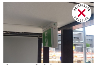
1.7.1 Firstly COORDINATE the set-out - make sure that air-conditioning units access panels do not clash with a light location (classic mistake), that all the access panels are shown.
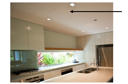
Above - access panel location dictated by the lighting set-out which dictated the fan coil unit set-out
Above - reviewing the design drawings and amending as necessary.
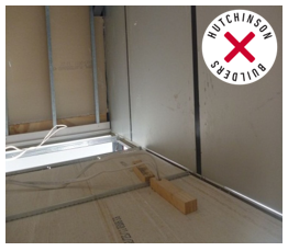
1.7.2 Set-out air-conditioning registers –ensure the Height considers the flange of the grille – the grille should typically be centre of a bulkhead, but many times the grille is setup to high and the grille is off centre OR the bulkhead is not large enough to use a setting angle on the soffits
1.7.3 Typically you will need the grille + 100mm top and bottom minimum for the framing under the insulated diffuser.
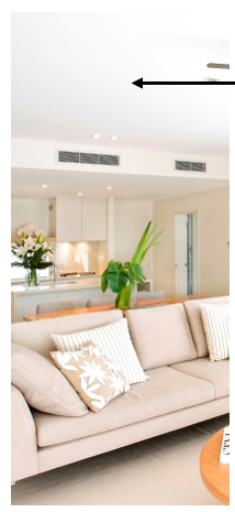
Above – centre grille on left, un-centred grille to the right
1.7.4 Framing should be set-out to avoid recessed lighting - you don’t want to cut framing and reduce support + there are clearances required by AS3000 Electrical Code – set-out the light on the slab for wall and ceiling lights and use a vertical laser to highlight lighting locations – the ceiling contractor then has no need to cut-out ceiling or wall supports by avoiding the set-out lights.
1.7.5 Before commencing framing ensure that you check the ceiling void is deep enough for the any recessed lights (e.g down-lights) where specified. If you have a 100mm cavity for the lights but the light is a 100mm+ 20mm clearance – ask the client to either drop the ceiling or look for a different light. Don’t wait until the lights are purchased and then discover they don’t fit. This can be a serious fire hazard and is often the cause of fire within the ceiling spaces.
1.7.6 Same for the transformer – make sure the transformer (usually electronic type) can be inserted in to the ceiling space. These must be clear of insulation.
1.7.7 Consider any areas with ceiling insulation and especially areas below concrete roof terraces or the like (refer External Waterproofing policy) which will have insulation and this will reduce the available cavity. Don’t cut the insulation away locally – the risk then is condensation directly above a light fitting!
1.7.8 Ensure framing is wide enough to accommodate any cavity sliders including additional batten/wall width to accommodate light switches/power point/lights located on the wall over the cavity slider door frame
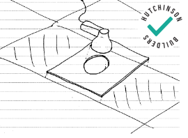
1.7.9 Ensure lights and other services installed into penetrations in grid ceiling tiles, are supported independently of the ceiling tile using sealed MDF or ply supports over the top of the T bar (see diagram below)
1.7.10 Ensure lights and other recessed fittings fit in the ceiling provided – lights installed hard up against slabs, insulation etc usually develops considerable heat and blow lamps and burns out transformers quickly. Make sure lights have some clearance and fit.
1.8 Construct suitable framing for movement joints as per section 2 below.
1.9 Construct noggings for support of other fittings and fixtures per section 5 below.
1.10 Provide an additional row of noggings for recessed timber skirtings per section 5 below.
1.11 Ensure the framing is constructed to provide support to sheets and setting angles on each side of corners.
1.12 Review structural steel connections details – a common framing issue is not considering the steel connection – affecting wall thickness to “cover” bolts connections, plates and so on. AVOID expensive structural steel changes or packing walls by preplanning and having the connections/walls setup for what is required up front – avoid delays, preliminary costs and rectification costs.
Walls
1.13 Battening walls is not just providing framing for linings rather than direct stick fixing! Battens should be used to STRAIGHTEN and SQUARE up the room. Block layers are not renowned for accuracy on set-out even when every corner is pinned by the surveyor.
1.14 Rooms should be set-out on the ground to ensure it is square, then battens installed in each corner and string lines or lasers used to infill intermediate battens – using either adjustable clips, or fixed batten clips with PVC window packers.
1.15 Rooms of a critical size (most bathrooms) should be packed out to achieve the required room size – this is very important on a high quality installation – using the ACTUAL tile sizes, complete a room tiling set-out to ensure that the room suits the tiles – yes – you can pack a wall up front to avoid a 10mm, or 30mm tile cut.
1.16 Complete a detailed room set-out – structural opening, tolerances, batten clip, batten, linings, tiles to get to an exact plumbing set-out centre of grout line/tiles etc as required. This is pre-planned prior to framing and everyone works off of it.
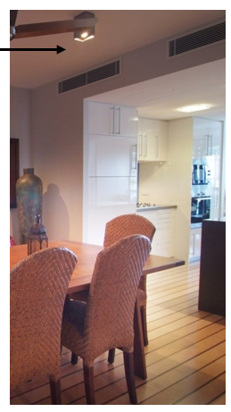
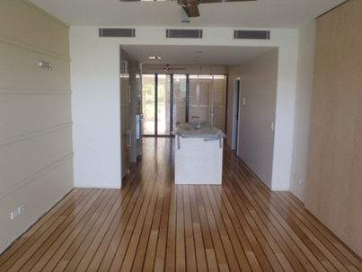
1.17 Obviously this is not going to happen in any project, or on every wall – so consider where this is CRITICAL which is all bathrooms (grout lines); and ANYWHERE there are floor finishes that have a linear finish – for example – timber floors, tiles (grout lines), carpets with lines in the finish – as the OUT of square walls will RUN OUT against the floor finish where it should be parallel.
Below – squaring up the walls of this unit for parallel was CRITICAL considering the floor finish
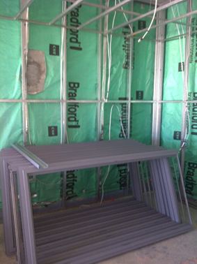
1.18 Ensure a CAVITY is provided between wall framing and external façade walls for 2 reasons;
• To maintain a moisture barrier to protect the framing and linings (particularly timber framing – mould/rot)
• To maintain ENERGY EFFICIENCY air gaps (refer to the project energy efficiency report for project specific requirements)
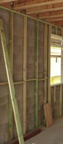
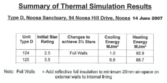
1.19 Check insulation requirements (thickness, type etc) of the specification and Energy efficiency report can be achieved using the width of framing detailed.
1.20 Any insulation installed on a perimeter wall must be protected from water
damage by a layer of sarking/insulation paper (including single skin construction).
Ceilings
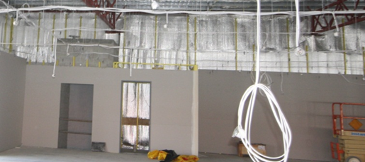
1.21 Battening of ceilings requires accurate installation with a laser to ensure the ceiling is level for 3 reasons;
1.22 Roof trusses, slab soffits etc have a tolerance in their construction that is not as high as linings – they are NOT accurate enough for lining, and furthermore may have deflection after installation which requires the ceiling framing to accommodate this difference in tolerance between the as installed truss and the required level of finish for the linings.
1.23 Where an out of level ceiling junctions with another element such as built in joinery (particularly the infill/shadow line), windows/pelmets etc which are known to be level/straight/accurate – the ceiling will “run out” against the other surface and the error will be highlighted
REMEMBER – a good straight, plumb, level well-built frame in the right set-out is the foundation for a good quality result for the wall and ceiling linings, supporting fixtures and fittings.