1.1 Waterproofing is required under Part F1 of the BCA/NCC and AS 4654.1 and AS 4654.2 (installation). It is an essential and genuine expectation of anybody involved in a building - the building owner, body corporate, consultant, BSA/regulatory authority etc - that the building will be waterproof. It is one of the MOST fundamental purposes of a building.
1.2 Balconies, terraces, podiums, plant room and decks may seem very different in appearance, function and construction, and may have very different finishes requirements – but there are several KEY similarities in respect to the correct waterproofing of these areas.
1.3 All of these areas in one way or another form a roof over another space – and as such many of the same principles used in a metal roof (see roofing policy) can be adopted. Key principles include provision of falls, drainage, overflows, anti-condensation, anti-capillary, correct product selection for application, care of the installed product, allowing for normal building movement and the like.
1.4 As a “roof” to either……
• an unenclosed (open) area and any finishes below it (in the case of a balcony, deck or some plant rooms); or
• an enclosed area with either habitable (living rooms) or non-habitable rooms (car park) below it (in the case of a roof terrace, podium or some plant rooms)
• all external areas need to be constructed ensure the areas below it are protected from water damage in the many forms it can take. The areas must be fit for their intended purpose and waterproofing is the only way we can construct roofs, basement, balconies and the like to allow them to be fit for their intended purpose.
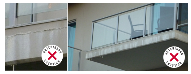
Calcium leaching down the external facades/slab edges of the building cause’s substantial visible damage that equally causes damage to our reputation. Waterproofing and design of waterproofing prior to construction is the only way these types of reputation damaging visual defect can be eliminated from our buildings. Refer to Section FF1.1 to 1.3 and FF1.4 of the BCA/NCC where the BCA/NCC requires the builder to construct in a manner that does not allow water or moisture to cause damage to the building. Although the BSA/NCC allows certain types of calcium leaching the tribunal and courts will not be as lenient.
1.5 The fundamental principles for building an external waterproofed area – or “roof” are:
1.5.1 The waterproof membrane is similar to roof sheeting. There are different types suitable for different applications. Some membranes are not suitable for high traffic. The correct membrane selection is very important – this is covered in more detail in section 2 below.
1.5.2 Most membranes are NOT designed or warranted to retain water (ponding) or be submerged – same as a roof sheet – so the roof needs to be built to achieve FALLS to take the water off the membrane.
1.5.3 Falls are to be formed in the substrate concrete pour regardless of whether there is a bedding layer over it. The minimum fall is 1 in 60.
1.5.4 The water needs to be COLLECTED by the roof membrane and taken to a gutter/drainage point for removal – either by “dishing” the entire area to a drain point (essentially a downpipe) or by falling the “roof” to a “gutter” for movement of the water to the drain point
The more central located the drain is, the shorter the distance to fall the slab and therefore the less thickness the concrete slab needs to be to create the falls (or the less likely the need is to put a fall in the slab formwork/soffit)
The “gutter” may be in the form of a spoon drain, a perimeter wall or hob, or a grated drain – so long as they CONTROL the direction of water flow towards the drain point.
1.5.5 CORRECT falls are rarely achieved as a result of poor design coordination/allowances for tolerances – or due to placement and finish quality in a concrete pour so minor adjustments are made as required PRIOR to membrane placement/application - topping/grinding to ensure accurate falls are achieved regardless of membrane, or applied finish (bedding etc).
A membrane will only perform as well as the substrate. If the substrate is delivered looking like a pool shell – guess what – expect a hefty repair bill for water leaks in the future.
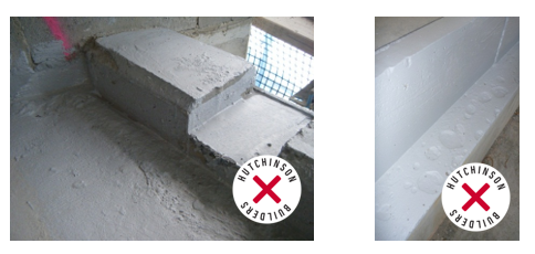
For a more technical definition – refer to the ARDEX description of required finishes for membranes at the end of this policy which essentially means a well compacted, smooth minimum class 2 finish with rounded/arrised /filleted edges.
No sharp edges, no back of the shovel finish, no un-vibrated areas.
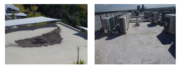
The substrate must drain. Don’t rely on the membrane as the membrane will be affected short term by water ponding.
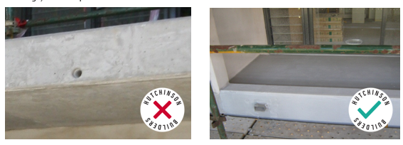
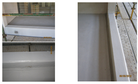
Above - Left - not acceptable.
Above - Right - Large unfilled blow holes - resulting in "ponding" - Unacceptable.
Above - Left - not acceptable.
Above - Right - A reasonable waterproofed rebate.
1.5.6 There are a number of possible finishes to external areas and it is easy to start adopting details used on one project on another without understanding the impact. To simplify this in respect to the basic requirements (see “Product selection” section for a table on suitable membranes);
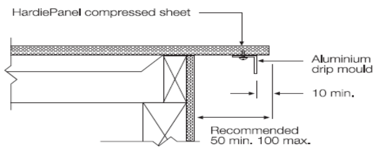
• Compressed fibre Balconies are designed with a one way fall with a 50 -100mm overhang and a drip angle – these are to be membrane waterproofed and direct stick tiled – refer system design by the compressed fibreboard manufacturer
• Similarly to the above - One way fall balconies MAY be installed with membrane and direct stick on the basis that there is a written signoff that the client accepts that the face of the structure will become dirty/water stained where no hob is provided. It is NOT permissible as a rule and must be approved by the team leader. If a hob is provided then the team leader may consider direct stick using slab preparation/s in lieu of bedding.
• Cross fall balconies MUST be installed with a bedding layer and hob (refer detailed DET- (multiply) drawings at the rear of this policy).
• ALL roof terraces and podiums with tiles - external areas over a habitable space – MUST be installed with a sheet membrane and therefore must be installed with a bedding layer and hob. Liquid applied membranes can only be used where approved by the Team Leader.
• All roof terraces, podiums, plant areas that have a trafficable membrane must be installed with correct structure falls, drains and a hob.
• One way fall walkways/sun shading /feature type areas (non-trafficable) MAY be installed with membrane and direct stick on the basis that there is a written signoff that the client accepts that the face of the structure will become dirty/water stain. Noting that a hob is not generally acceptable in these areas from a design perspective – see detailed requirements for these areas under “DECKS”.
1.5.7 The bedding provides a tolerance layer between the imperfect concrete substrate and the tiles to ensure the tiles are laid on an accurately screeded substrate with correct surface falls. Bedding ensures that tiles are laid to a good quality alignment (up and down) and to the correct falls to prevent water ponding – accounting for the many various tile formats (tile size) and patterns that affect the ability to lay tiles to the correct falls beds must be laid to provide proper drainage to the finished surfaces levels of the tiles area/s.
1.5.8 Bedding does not achieve 25mpa as required under the Australian Standards and therefore waterproofing CANNOT be applied over the bedding under this strength. Waterproofing goes UNDER the bed.
1.5.9 All areas with a tile bed MUST have hobs –– for 2 reasons:
• to avoid surface water collected by the external area flowing OVER the edge and causing damage below and creating water/calcium/dirt/mould stains the face of the façade below and;
• to “contain” the edge of the tiles and bedding to avoid aesthetic look of the exposed bedding (regardless of any attempts to provide a finish to this) and to avoid the inevitable water penetration to the cold joint between the concrete substrate and tile bedding from leaching through the façade with efflorescence (created from the lime in the bedding + water). Calcium leaching over or through the balcony edge will no longer be permitted on any Hutchinson Builders buildings. Do not build without hobs to any areas where the below could occur without prior approval of the General Manager.
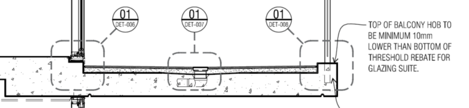
1.5.10 Hobs are to be poured integral/monolithic to the slab and be a minimum 75mm high x 150mm wide (to guarantee its structural integrity against cracking etc) See DET005 for more typical hob details.
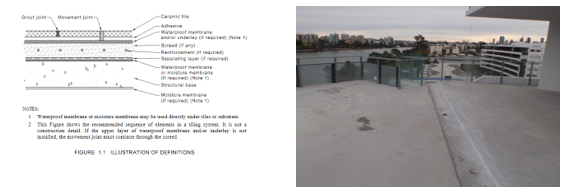
1.5.11 Where all falls are provided towards the edge of an external area, Hob less construction is the like as gutter less roofing – useless - as surface water falls over the face of the façade and substrate water leaches out of the cold joint as noted above which cause damage to our reputation and the repair costs are non-acceptable and repair is often not reasonably possible. Ask yourself would you accept the calcium damage on the deck edge shown in the above photos if this unit was owned by you – The answer is NO.
1.5.12 Where falls are provided away from the edge of the external area (towards a central drain for example as shown in DET005), Hob less construction is like a box gutter with low sides – still useless - as it only contains a small amount of collected water (the depth of the falls of the area) before surface water falls over the face of the façade and substrate water leaches out of the cold joint as noted above
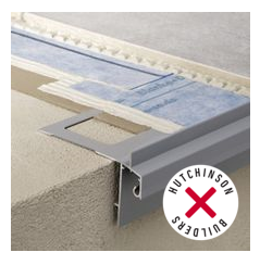
1.5.13 Direct stick drip moulds and Hobs are not to be formed by using Aluminium balcony edge tile trims without subsill drainage ability - these products are NOT to be used on any of our projects.
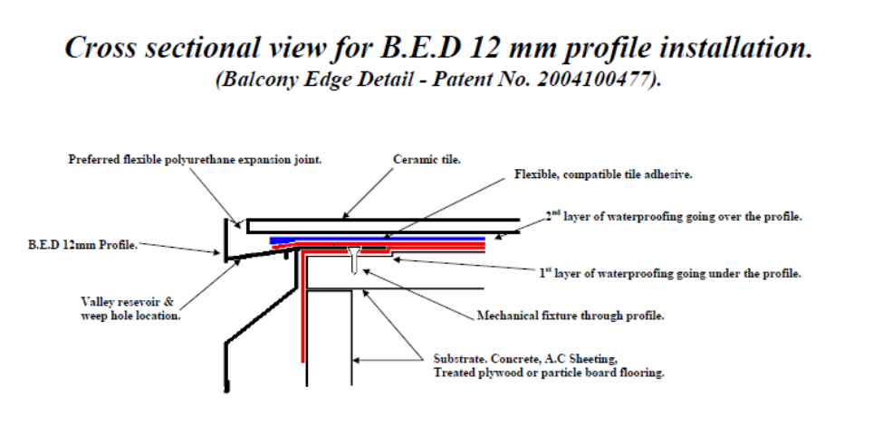
1.5.14 Aluminium edge trim with substrate drainage ability are to be reviewed on case by case basis by the team leader and must be installed correctly with properly prepared concrete balcony to falls.
1.5.15 Hobs need to be 20mm minimum LOWER than the internal building area floor level to provide overflow protection. If hobs are higher than the internal floor area, then overflows large enough to readily discharge general debris (leaves etc) and designed by a hydraulic engineer at 1 in 100 year storm, and then increased 50% for potential blockages from debris, and with 100% redundancy (i.e. provide twice as many as required by the design) MUST be provided.
Above - 50mm spitter/overflows in balcony where the hob was higher than the internal level – replaced with 100 x 50mm spitter/overflows
1.5.16 Drainage MUST be designed by the hydraulic engineer and provided to remove stormwater in a controlled manner with a minimum 3 degree fall – this needs to be controlled closely with cast in drainage. The drain must be the LOWEST part of the external area.
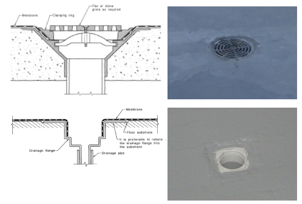
1.5.17 The drainage point must permit the membrane to turn down into the drain – using a membrane clamped drainage outlet (for trafficable/exposed membrane areas like plant rooms), or a puddle flange RECESSED into the floor (in tiled terraces or balconies)
1.5.18 When using a puddle flange – use a WONDERCAP or equivalent system for surface drainage, substrate drainage and a temporary cover to prevent slurry/bedding blocking the drain.
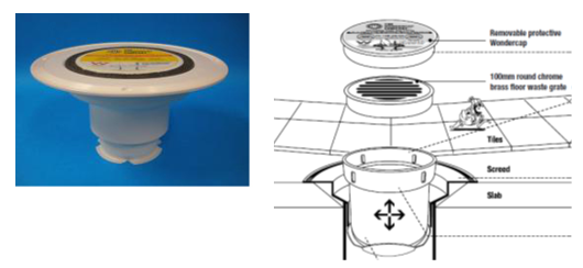
Above - Wondercap - See also DET05 & 09
1.5.19 Wondercap puddle flanges will be used on all decks and will remain capped until tiling is complete – no duct tape, newspaper stuffed in the pipe, or the like is permitted. Use the proper hard cap.
1.5.20 Drains will be checked with either a camera or mirror for rubble and concrete past the bend and signed off and tested on completion.
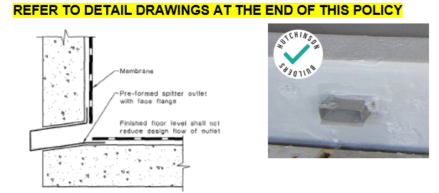
1.5.21 In the case of drainage using spitters – the membrane must be turned in to the spitter.
1.5.22 Balcony spitters will contain a 3 degree downwards pitch and will extend a minimum of 50mm past the outer finished face of the balcony.
1.5.23 Drainage and spitter drainage systems are typically designed at 1 in 20 year rain events – so all areas MUST be provided with a 1 in 100 year overflow
1.5.24 As noted above either use a hob that is lower than the inside floor level of the building or by using an overflow through a hob, or wall for example – the detail of which is similar to the above – membrane turned into the overflow.
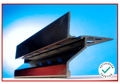
1.5.25 Provide Anti capillary breaks – drip grooves/angles wherever there is an exposed soffit.
1.5.26 Ensure engineering of the external areas are designed to minimise cracking.
1.5.27 Reinforcement- post-tensioned and conventionally reinforced slabs in large areas may suffer from “thermal shock” – requiring a layer of non-structural mesh to minimise surface cracking to slabs and tile beds/screeds.
1.5.28 Procure written advice on expected movement of any construction joints – this will affect the waterproofing system used over the movement joint (typically on podiums) for large projects where the floor area requires 2
or more slabs to be poured for the one area
1.5.29 Provide these details to the waterproofing supplier. The waterproofing supplier will provide waterproofing joint details consistent with the engineer’s details. The waterproofer will provide waterproofing manufacturer’s specifications and details relative to all joints based on the engineering details.
1.5.30 Movement joints are waterproofed in a number of different ways dependant on the use of the area where the movement joint is located and the expected stress caused by normal building movements including thermal and ground movement’s.
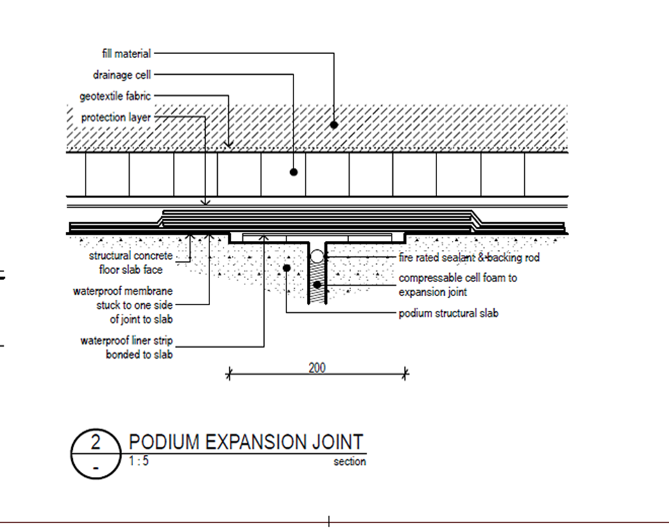
1.5.31 The final control joint detail will be approved by the Team leader prior to proceeding.
1.5.32 All podium slab penetrations will have a wonder cap puddle flange installed in all waste locations. Flanges will be capped at all times. Conrad from the Wondercap Company 0433551599 has offered to provide specific advice and prices to Hutchies sites.
1.5.33 The puddle flange will be recessed into the slab to maintain 1 in 80 falls to the outfall.
1.5.34 Drains are to be tested on completion.
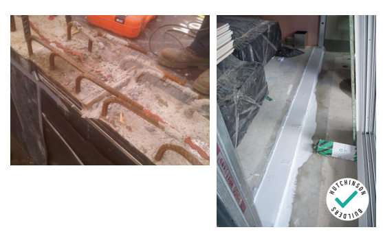
1.5.35 Penetrations in external areas are the same as the perimeter – they need a hob.
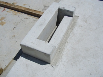
The structure to the left is for refrigeration pipework to penetrate the deck and turn over 90 degrees. The lowest point of the penetration must be higher than the over flow or it will BE the overflow and the building will be flooded!
1.5.36 Walls will not be penetrated within 300mm of the balcony floor. Penetrations will be drilled on a minimum 33 degree angle with the low point outside and will be sealed with paintable Polyurethane sealant prior to painting.
1.5.37 Recessed light fittings or the like are to have the recess pocket formed with a fall to the outside on the bottom and then waterproofed prior to fitting the service – these areas provide areas for water pond. Sealant around the light is not sufficient to prevent water ingress.
1.5.38 Provide plinths for plant to be mounted on external areas to keep it out of any surface water.
1.5.39 Where external areas are constructed using Compressed sheet –
• Provide a 50mm over hang and that will have a 12mm x 12mm drip mould on the outermost edge.
• Sheet decks will contain a 1 in 100mm fall.
• All sheet joins will be supported by a 45mm wide member as per sheet manufacturer’s details and they will have an expansion gap.
• Tiles must contain control joints at all sheet joins.
• Refer manufacturer details for supports and fixings + edge details
1.5.40 Ensure all tiles are installed using correct size notched trowel as per AS3958.1 and that expansion joints are provided to suit the structure and the size of the tiled area.
1.5.41 Ensure the membrane at the handrail installation point is not damaged during installation. Core filled handrails must be epoxy filled to underside of tile or render as applicable and then polyurethane sealed to avoid water ponding around the hand rail post. Refer AS4650.2 for detailed requirements for penetration through membrane (see below).
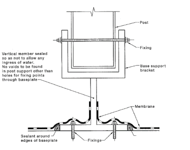
NOTES
- The membrane should be turned up around the post or support prior to membrane installation.
- All post bases should be placed into position to placement of membrane. If posts are placed onto a completed membrane, any damage membrane should be replaced or repaired to ensure its original integrity.
- For posts penetrating through the deck, see Clause 2.8.4.
- All penetrations into concrete should be treated with epoxy. All fixings into concrete should be of a chemically injected type in order to maintain the integrity of the waterproofing and substrate.
- Consideration should be given to post designs that are fixed below the level of the deck without penetrating through the surface of the deck.
- Waterproofing of the system will be compromised by the use of timber or metal posits that are not suitable for external use.
- For base support to heavy structures or plant, extra consideration should be given to waterproofing and sealants to cater for the vibration movement around the base of the installations, such as-
a) heavy plant and equipment and plinths;
b) power poles;
c) flagpoles;
d) communication towers;
e) roof acess railings; and
f) building maintenance units.
1.5.42 All external areas to be waterproofed will be clean and free of dust prior to membrane being applied.
1.5.43 Review the entire areas for CRACKS and treat these accordingly – cut out and polyurethane/bond breaker – advise engineer and have inspected PRIOR to waterproofing
1.5.44 Waterproof the entire external area (do NOT just bandage the perimeter!) – including upturning at walls with a suitable termination detail where the membrane finishes; and waterproofing over the entire hob and extending this down the face of the hob outside the external area and down into the drip groove/angle in the soffit below
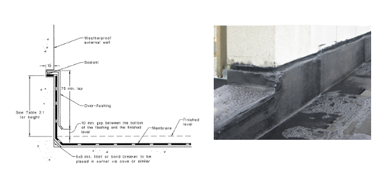
Waterproof to floor, hob face of hob (façade), into overflow/spitter
1.5.45 Provide reflective foil backed anti-condensation insulation under “roof areas” being external areas with enclosed spaced below them (roof terraces, podiums, some plant rooms – NOT balconies). This is mechanically fixed to underside of the soffit.
1.5.46 Refer ICANZ for more information on insulation
http://icanz.org.au/
1.5.47 Concrete has virtually no thermal properties – so the sun will heat the slab up and it will get warm all the way through to the soffit. This warm soffit in a cold air-conditioned enclosed space (like a unit, or office) is going to affect the efficiency and effectiveness of the operation of the air-conditioning.
1.5.48 The warm air created may also provide a source of moist air that leads to condensation on the ducts; grilles etc (refer air-conditioning policy). At night as the slab cools, it will draw cold in that may drop BELOW the air temperature inside the building and condensation would then form on the underside of the slab.
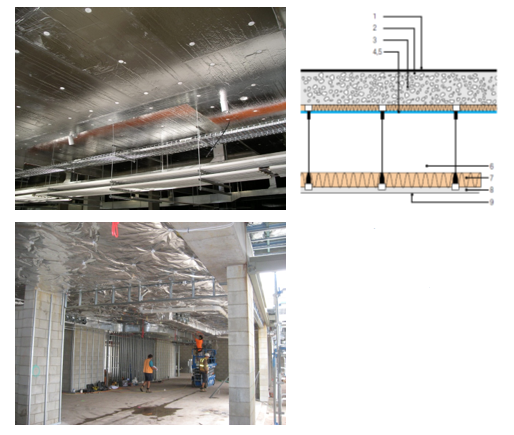
- Ourdoor Air Film
- Roof Water Proofing Membrane
- 150mm Concrete Slab
4,5 Reflective Insulation Material R-Value - Unventilated Reflective Air Space (>100mm, <600mm)
- Ceiling Insulation
- 10mm Plasterboard
- Indoor Air-Film (Non-Reflective Surface)