2.1 CONDENSATION - DRAINAGE
Condensation is a major cause of water damage inside a building. Sometimes referred to as the “dew” point, it is the point at which the water vapour condenses to a liquid.
2.2 Air-conditioning systems dehumidify or extract water from the air when they are producing cold air, meaning the humidity in the air is made cold enough for the water in the air to condense into a liquid form of water.
2.3 Boil water and steam is produced. Now cool that same steam and it turns back into water. So as cold water or ‘Condensate’ is a by-product of making cold air it needs to be captured and taken out of the room in a controlled manner. We do this with condensate drains.
2.4 As the water is cold in the condensate line, it is important to insulate the outside of the pipe to prevent the cold water inside the pipe cooling the pipe to a point that the warmer moist air around it condenses on the outside of the pipe dripping onto the ceiling and out through lights or absorbing into the ceiling linings.
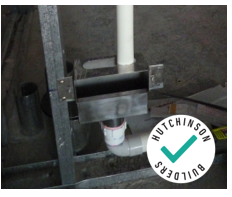
2.5 All FCU’s have a graded base to catch condensation and discharge it to a condensate drain. Most FCU’s do not have a secondary “safe tray” so it is essential to provide this drained metal safe tray to catch condensate that may not be collected by the inbuilt graded unit base. Please do not let anyone convince you it isn’t required!
2.6 A drained secondary safe tray of min 50mm depth under the entire fan coil unit is the equivalent of an overflow on a roof. ABSOLUTELY NECESSARY.
2.7 Water must not pond in the tray
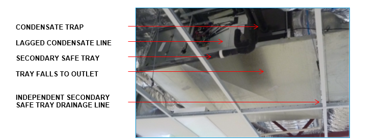
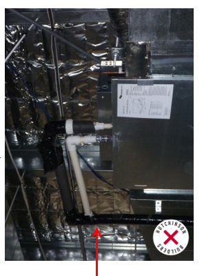
Above - Typical Ceiling Mounted FCU
2.8 Ideally you want to drain the condensate lines by gravity alone making the need for sufficient ceiling space essential.
2.9 Unfortunately building height limits, ceiling heights and budgets constraints usually mean there is very little ceiling space and as a result, there is not enough space between the bottom of the fan coil unit and the top of ceiling framing to gravity drain the lines. In this case condensate pumps are used. (Pumps are often provided as standard in many of the smaller fan coil unit models)
2.10 Condensate pumps are simply a small electric pump (usually 12v) that pumps the condensation drainage from the bottom of the fan coil unit up far enough (usually they can reach around 500mm) to allow the condensation to be transferred to a gravity drainage system. Using a condensate drain is similar to putting a sump pump into a box gutter without a downpipe. NOT IDEAL AT ALL. Condensate pumps regularly fail or get blocked. It is another piece of equipment that can break and if it does, can create significant damage.
2.11 AVOID condensate pumps where ever possible with sensible preplanning as early as possible in the design process. Resistance from clients to increase building height; or lower ceilings is always the issue, particularly if they are on-selling the property and are not concerned about the ongoing issues that they can walk away from and leave the builder to deal with for years to follow.
2.12 In the event condensate pumps are necessary - ensure the FCU’s are setup so that in the event of a condensate pump failure the FCU stops operating or at the very least cooling (and therefore stops making condensate water/moisture) when using a float switch provided by the manufacturer.
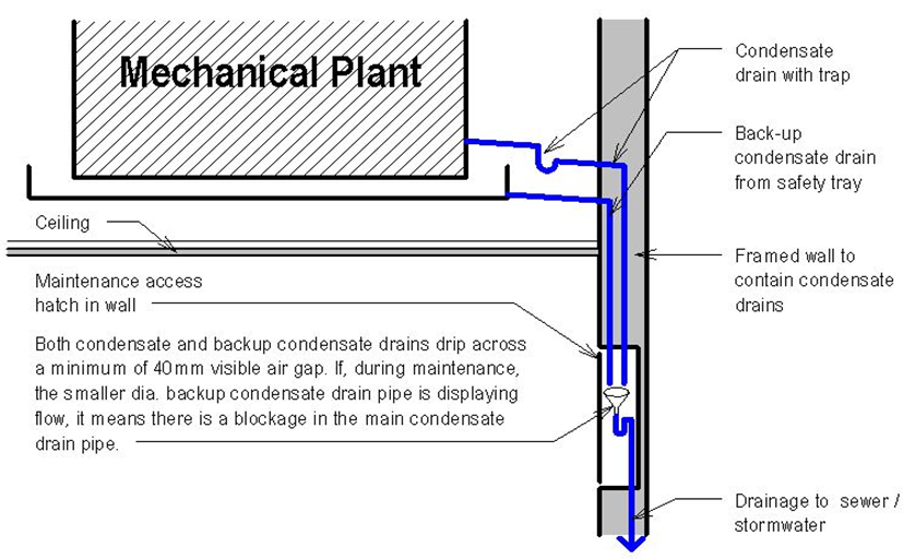
2.13 Condensate drains can get blocked with debris such as ice and algae build up so they need to be at least 25mm diameter solvent jointed UPVC (not electrical conduit) fully lagged (with glued insulation - the taping of the insulation is only to hold it in place until the insulation glue sets) all the way back to a tundish located in an accessible riser. The secondary safe tray and condensate drains should be plumbed using separate lines to prevent blockages from causing damage allowing the water an alternative route to the tundish.
Above- Typical FCU Dual Drained with Secondary Safe Tray
2.14 Where multiple units are hooked to the one condensate line, each FCU unit should be fitted with a clear vision hose at the unit to ensure the unit can be checked for correct operation. This applies to both condensate AND the safe tray. If there is no water running through condensate line, but there is water running through the safe-tray – then that is the unit that has problems.
2.15 Care must be taken on installation not to flex the safe-tray or condensate brazed spigots it will crack and cause a leak. This happens more than you think and is in many cases the cause of leaks and major damage.
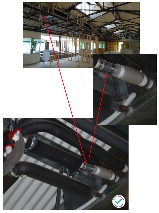
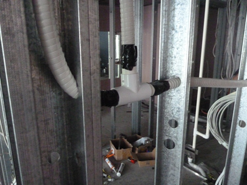
2.16 Adequate support to the condensate and safe tray drainage lines is required – supporting trap and both lines adjacent the connection of the tray is critical to avoiding damage to the tray/FCU connection spigot.
Below - support of condensate at the trap
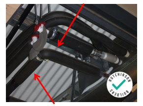
Above - support of drainage line
Above no supports installed as yet.
2.17 Tundishes are connected to sewer or stormwater depending on local council requirements which may change from time to time. You need to check with your local council for each project at commencement.
2.18 When the tundish is connected to stormwater it must be located higher than the stormwater overflow such as a rainwater head, gutter or an open grated drain. It cannot form part of a sealed stormwater system or you risk water back flowing into the building.
2.19 When a tundish is connected to sewer it can be a maximum 2.5m from a plumbing stack or 10m from a floor waste gully under the plumbing code AS3500. This limits the placement leaving the Air-Conditioning Subcontractor to run the condensate and safe tray drainage from the FCU to the appropriately located tundish.
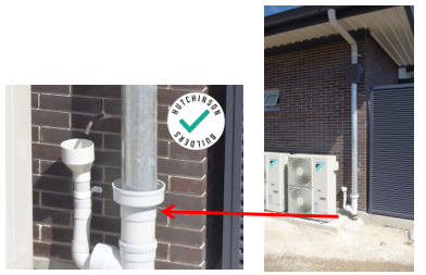
2.20 The tundish itself is typically 2 ½ times wider than the pipe they are connected to. They act as a funnel to catch the water dripping from the condensate pipe. An air gap from the bottom of the condensate pipe to the top of the tundish allows for visible inspection that the line is draining freely. The plumbing code requires 2 times the internal width of the condensate pipe for this air gap so around 40mm for a 25mm condensate line is ideal.
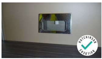
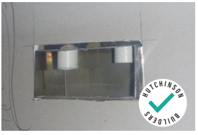
2.21 Tundishes must be accessible for easy inspection and maintenance/flushing. They can be surface mounted under a sink (so long as they are not plumbed into the trap of the sink or they will become an overflow to the sink and spill water into the cupboard), or recessed into a wall (behind a fridge in a kitchen, or in an office wall for example).
2.22 Recessed wall Tundishes available in the market are a complete sealed unit fitted prior to sheeting.
2.23 In-wall condensate lines need to be isolated from the frame and adequately supported and not kinked or in any way installed against sharp objects – we need to avoid anything that has a potential to cause a leak.
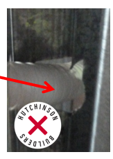
Above - framing cut out poorly - sharp edge will damage line
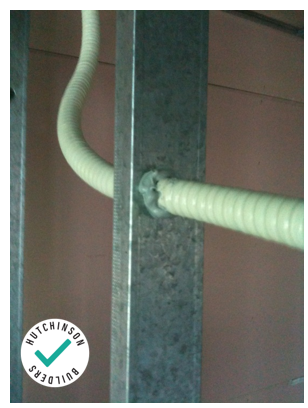
Above - well installed and isolated
2.24 Ensure condensate drains are water and/or pressure tested for 4 HOURS prior to closing up walls and ceilings.
2.25 CONDENSATION – SURFACE (SWEATING)
2.25.1 Surface condensation is caused by differential temperatures between air and various surfaces
2.25.2 Using the façade as an example – like the windscreen of a car - If it’s warm outside and cold inside, water may condense on the outside of glass. It follows that if it’s cold outside and warm inside, water may condense on the inside of the glass.
2.25.3 Buildings suffer from surface condensation in principally two areas –around supply air registers (grilles) and around ducts.
2.25.4 If a room is set at 21 degrees, the air coming out of the grilles is going to be as low as 10 - 15 degrees and as we all know, hot air rises, meaning the combination of hot air (produced by the sun heating air through windows, radiant heat etc) which contains humidity - is in contact with the ceiling (producing a warm ceiling), will result in condensation and free water on the grille.
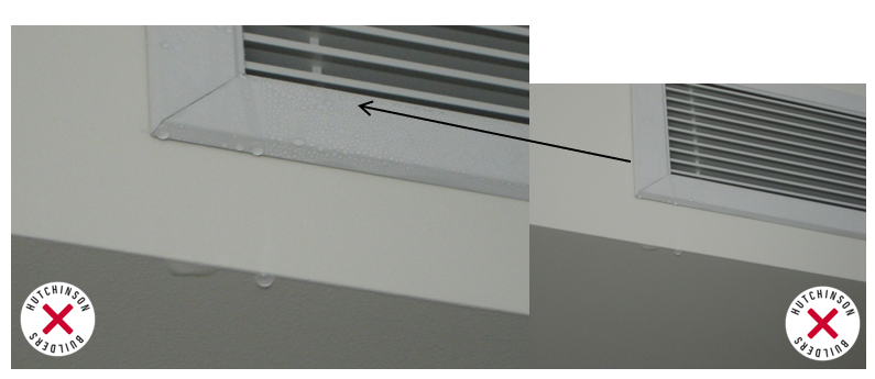
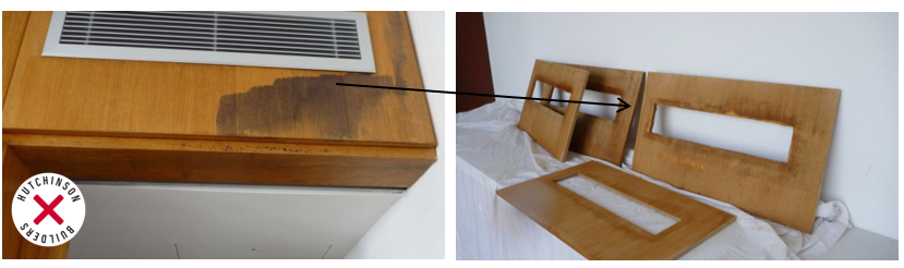
Above – condensation over timber veneer panels can easily water stain the timber
2.26 Insufficient ceiling insulation along with roof and wall cladding and lagging of the supply air register cushion heads or ductwork will promote the warm moist air of the ceiling void to condense on the flexible or exposed metal duct which has been cooled by the passing air. This often runs off the ductwork onto the ceilings or out of registers, damaging finished surfaces below.
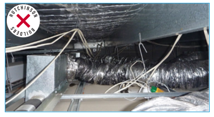
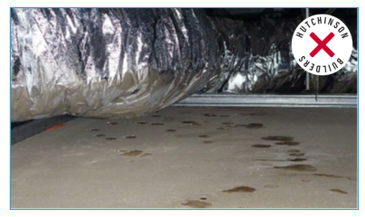
Above - Ductwork ‘sweating’ onto plasterboard ceilings due to poor or damaged insulation
2.27 The Building Code of Australia section J 5.2 has prescriptive requirements for insulation of ductwork and specification J5.2.3 provides R values to be achieved based on duct location and class of building. This has changed every BCA/NCC for the past 5 years and therefore it cannot be assumed the drawings are correct. This affects condensation – the further north towards the tropics, the worse this problem becomes.
Above –external insulation being fitted to ductwork properly.
2.28 Avoid using adjustable grille blades as this permits the owner of a unit to point the very cold air toward a concrete soffit, and since concrete provides little insulation, this will result in a cold floor in the space above, and cause condensation and mould growth in the surface above. In a strata title situation, this can be a real problem. The upper unit could have a cold, moist, mouldy tiled or carpet floor with no way of stopping it as the cause is from the unit below. This situation can be unfixable as the owner below may refuse to allow the grills to be redirected.
2.29 If any of this is happening consult your Team Leader or the Hutchies Green Team urgently for advice. The way to solve it starts at the design phase by providing a well-insulated roof, façade and ceiling system. In tropical areas, a mechanical system capable of dehumidifying the air adequately will be essential and require substantially higher capacity units effecting not only cost but also the maximum electrical demand. Some common ways to improve this common problem are;
• Increase the unit set point temperature – instead of allowing the user to set it as low as 16 degrees, change the thermostat so it is no lower than 23 degrees. This may show 16 degrees on the thermostat but the compressor stays at 23 degrees.
• Seal the room effectively to the outside air including the use of door and window seals. Consider fresh air intake as part of this action.
• Use windows/door sensors to control the timing of the Air Conditioning. If a door is left open for a period of time the system turns off to reduce the chance of ‘sweating’.
• Add insulation to the ceiling.
• Add shading to windows thus reducing the thermal / solar load entering the building.
• Tint the glass with reflective film or provide performance glass. Often more costly glass, but it provides greater thermal insulation.
2.30 Ensure the Air Conditioning system is designed to cater for all actual heat and solar loads. Ensure that all specified shading and thermal insulation systems are completed. Where changes are made during construction, update the Mechanical Services Design Brief to avoid long term temperature control issues.
2.31 Laundries in class 1 and 2 buildings are a unique issue. Refer the Interior Waterproofing policy for further information. Essentially the clothes dryer type determines the exhaust design.
2.32 Systems to be operation 24 hours a day, or linked to a timed switch to ensure the fans run for several minutes after the light switch is turned off and hooked through a relay to provide a second input to operate the fan – a thermal sensor is to operate the fan if heat builds up in the laundry. If the dryer is operated without a light on, the fan will exhaust once temperature builds up.
2.33 Refer to the waterproofing internal areas policy in respect to this issue.