4.1 GENERAL
4.1.1 Flood test all membranes – bund the drainage outlets/spitters and fill the external area with water – observe leaks/loss of water or membrane bubbling.
4.1.2 Testing of waterproofing membranes prior to finishes such as bedding and tiles is to be completed using Micrometre and Porosity detector or a section of membrane is to be cut out and tested/measured as part of the waterproofer’s inspection and test procedures.
4.1.3 The major flaw with Liquid Applied Membrane’s (LAMs) is the dry film thickness is rarely applied to the manufacturers minimum tested thickness requirements. This has a major impact on the life and performance of the waterproofing over the short term and is often a significant contributing factor to many failures that cannot be visually observed by onsite staff. Determine how you and the waterproofer are going to confirm the dry film thickness as part of quoting process. Ensure the waterproofer does not use Xylene to thin the waterproofing. Xylene should only be used in circumstances where the membrane needs to be reactivated i.e.: a podium started on a Friday night to be finished on a Monday allows the membrane to set/harden. The Monday waterproofing will not bond to the overlap on the Fridays waterproofing unless reactivated. This may also be relevant where a sliding door reveal is waterproofed prior to door installation and the deck is done months later. Discuss this with the supplier/manufacturer.
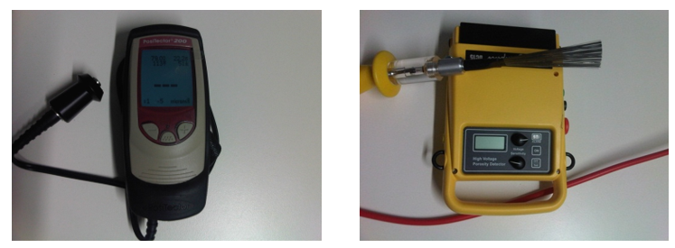
Above Left - Micrometer to Test Coating Thickness.
Above Right - Porosity Detector.
4.1.4 Provide suitable barriers to prevent traffic over membranes during construction - traffic risks damage to membranes.
4.1.5 Prevent works being carried out over the top of membranes unnecessarily – protect membranes at all times where it is necessary. Inspect all waterproofing prior to bedding/tiling to ensure the waterproofing has not been accidentally damaged.
4.2 FACADES
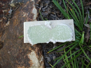
4.2.1 Where tiles, stone cladding/porous finishes area used on a façade – the substrate shall be waterproofed.
4.2.2 Check compatibility of any finishes applied to the membrane – epoxy glues for tiles – and check the PULL off strength of the membrane for the weight of the finish applied to the membrane. If a 10mm stone tile is glued to a membrane, the membrane needs to be able to have enough adhesion to withstand the weight of the façade/tile system.
4.2.3 Ensure the top of the façade is waterproofed to ensure that water does not get behind the façade membrane (preferably metal capped if possible) and cause failure of the adhesion system.
4.2.4 Ensure plastic tile spacers are removed (these channel water into the façade) and caused the tiling to be rigid and prevents normal expansion and contraction of the tiling system. AS3958.1 requires that all plastic spacers be removed prior to grouting. The result of the spacers being left in the wall is shearing of the waterproofing and or adhesive due to thermal shock/expansion and contraction of the tile system. Plastic spacers must be removed from all tiling that is exposed or could be exposed to sun or heat.
4.3 SAFETY
4.3.1 Ensure services such as power points, gas valves, hose taps; as well as windows with louvers etc are constructed far enough away from the balustrade, or in such an manner to NOT facilitate climbing a balustrade.
4.4 TILING
4.4.1 Tiles to external applications will be selected and tested to achieve the required slip rating under the Building Code of Australia.
4.4.2 Tiles will not be direct stick applied to membranes unless approved by the Team Leader.
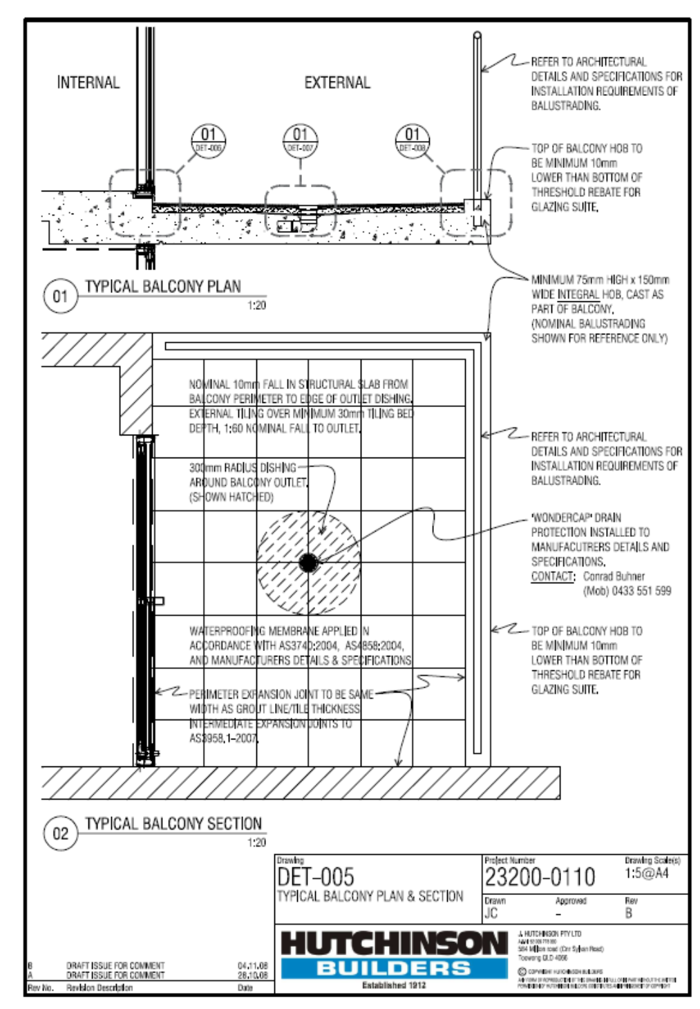
4.4.3 The tile beds will contain a 1 in 60 fall to the waste/s and will be a minimum of 15mm thick and will be reinforced when in excess of 50mm.
4.4.4 The tile bed will contain a perimeter control joint (able-flex) to all sides. The joint will be a minimum of 8mm wide and will extend the full height of the tile bed.
4.4.5 Tiles will contain a full perimeter control joint and will contain intermediate control joints every 4m internal (2m for terracotta or external tiling). Control joints will be clear of grout/adhesive and will be the full height of the tiles and adhesive.
4.4.6 All control joints will be sealed with a masonry sealant. The flexible seal will be a minimum of 8mm deep and will contain a concave. Backing rods are recommended in deep joins. Sealant used must be mould resistant.
4.4.7 Tiles around the waste will be cut to obtain falls if the tiles are 150mm square or larger where falls cannot be achieved to prevent ponding. Tiles should be set out and pre-planned to avoid cutting tiles where possible. Tile lines inside to outside and set out must be under taken and planned prior to the commencement of bedding and tiling to avoid cutting tiles and to avoid visual tile impacts.
4.4.8 Tiles will contain a minimum of 100% adhesive coverage. Note AS3958.1 specify different notch trowel size for different tile size.
4.4.9 Finished tile levels will remain 15mm clear of the base of any sub sills or window or door weepholes – refer windows and doors policy.
4.4.10 All tile spacers will be removed prior to grouting. This is to be inspected by us prior to grout application.
4.4.11 Tiled deck surface falls will be tested on completion and signed off. Water will not pond to any area of the deck surface.
4.5 GLAZING
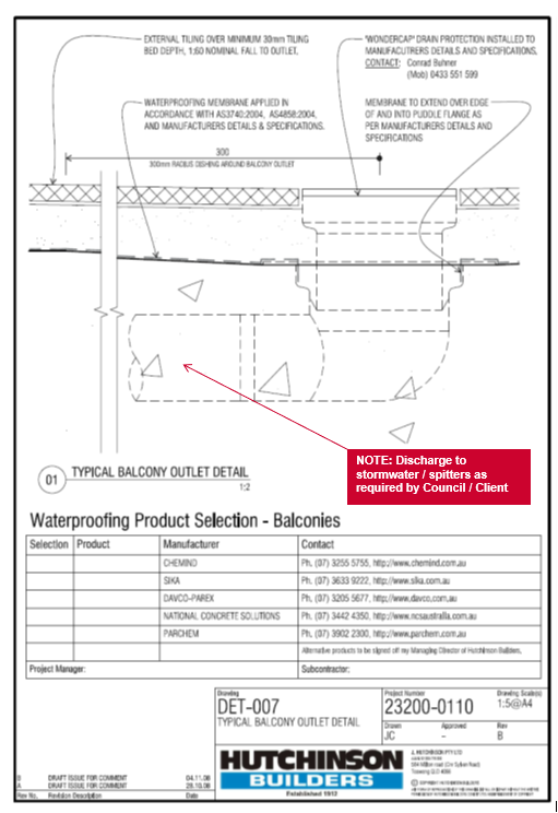
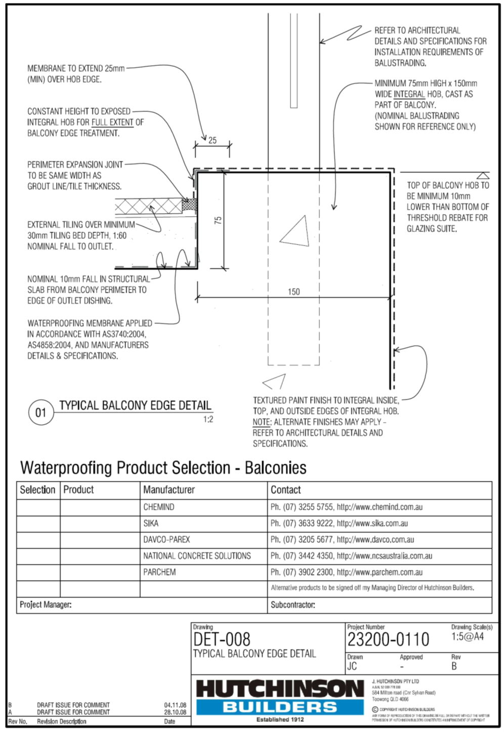
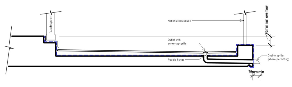
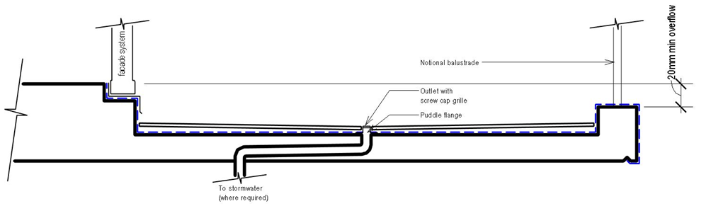
4.5.1 Holes will not be drilled through the membrane for balustrade post installation. Provision will be made in the hob for post connection prior to waterproofing.
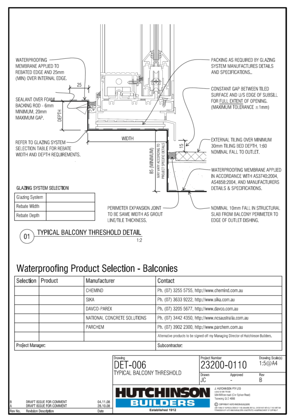
4.5.2 Sills to door openings will be rebated into the slab consistent with manufactures requirements prior to water proofing the door opening.
4.5.3 Sills to window openings will be rebated a minimum of 25 mm or a 25mm angle installed to the inside of the external wall prior to waterproofing the window opening.
4.5.4 Unless chemical anchors are used or holes are pre drilled and sealed with polyurethane sealant prior to installation of fixing, no holes to be drilled in the membrane at any point in construction including window and door sills. Refer to the window and door policy.
4.5.5 The junction between the outer face of the rebate and inside sill of the door will be sealed with polyurethane sealant.
4.5.6 Render will be “V”groved and will not contact the window frame. The junction of the window and render will be flexible sealed as per AS2047 and the window and door policy.
4.6 BALUSTRADES
4.6.1 Refer BCA/NCC volume 1 D2.16/D2.17 and BCA/NCC Volume 2 (domestic Class 1) part 3.9.2 prescribed handrails
4.6.2 Balustrades are required under code to be 1000mm minimum high for all applications. Measure this from the TOP of a hob as a precaution, account for expected floor finishes and to be sure set handrails at 1050mm. There is little issue with having handrails slightly higher than the MINIMUM.
4.6.3 Balustrades configurations are be spaced at 125mm max clear opening.
4.6.4 Balustrade may incorporate horizontal balusters for handrails used where the fall from the FLOOR height to the surface below is less than 4m. If the fall is 4m or greater, then there can be NO elements between 150mm from the floor to 760mm from the floor that facilitates climbing.
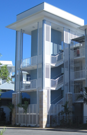
4.6.5 Below – horizontal batten screens with non-climbing sections at the handrails – additional battens used with 5mm between battens at stop climbing of the battens. Other handrails using vertical balusters only.
4.6.6 Wire balustrades have a high initial failure rate and a disastrous long term compliance failure rate – it is strongly recommended these are NOT installed. Where they are required to be installed notwithstanding every possible protest, ensure a clear written instruction to install these is provided AND the maintenance manuals advise the building owner of the need to test for compliance regularly and adjust wire tension to ensure compliance. Wire balustrades must only be used with approval of the design by the Team leader.
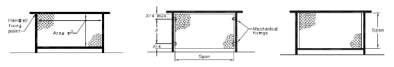
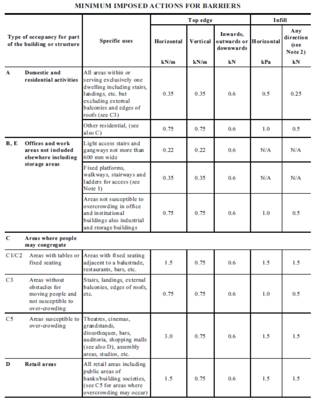
4.6.7 Balustrades must be engineered for the anticipated load – domestic applications require a different load to a retail void or stadium barrier handrail/balustrade that might have dozens of people against it - the standard for design is AS1170.2 (this means the balustrade must be engineer designed) – and this provides different handrail and infill loads (see next page) and Glass balustrade infill design requires that a handrail to remain in place as fall protection even if a glass panel is broken and that glass infill’s be designed to AS1288 to meet the loads determined by AS1170.2.
Interlinking handrail The handrail is non-load-supporting, unless a panel breakage occurs, and is connected to adjacent panels of glass, or the building, where the adjacent panels are at least 1000mm wide and three or more panels of glass form the balustrade. If any one panel fails, then the remaining panels and handrail shall be capable of resisting the loads defined in Clause 7.2.1 and 7.2.2.
4.6.8 There are several options for this such as those noted in AS1288
4.6.9 The glass selection is also important – toughened, laminated, laminated heat strengthened are options – each with pro’s and con’s for safety, edge delamination (Laminated glass) etc for consideration by the designer - make sure the CERTIFIER and BUILDING owner are a part of the design process to ensure the correct balustrade type is selected to code and for the intended use/application
4.7 WARRANTY
4.7.1 Waterproofing warranties are typically written such that there is very little chance of a claim being recognised and if it is – it is limited to minor repair work. They typically do not cover CONSEQUENTIAL loss. They will fix the membrane, but not the damage that the leak causes.
4.7.2 There are some companies that offer a Consequential damages warranty. These forms of warranties require the use of the manufacturers specified products (not the cheapest products), strict inspections by the manufacturer + a cost of approx. 1% of the waterproofing contract value to pay for an insurance policy that has as many conditions as the warranty itself (out clauses) with the insurance policy set at a pre agreed maximum claim value of around $1m.
4.7.3 Get a copy of the proposed warranty for review and acceptance by the client BEFORE approving the use of any products.
4.7.4 Ensure the proposed subcontractor is a licensed applicator and provides details of their product supplier/manufacturer. Applicators must not use different suppliers. The system must be approved prior to commencement of waterproofing and any changes must be approved by the Team Leader prior to application of those changes.
4.7.5 It is MANDATORY to arrange for the membrane manufacturer to visit site regularly to inspect works to ensure compliance.
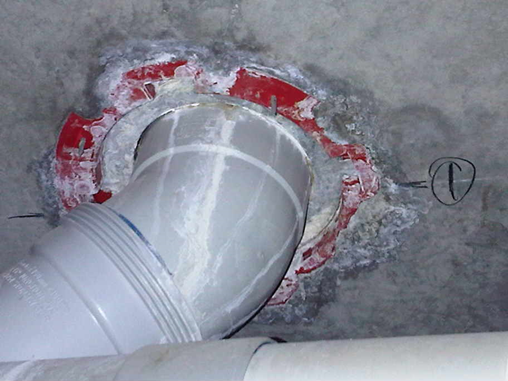
4.7.6 A commonly unseen consequence of water damage – rusted out fire collars. This fire collar is no longer compliant and will required full replacement to comply with the BCA/NCC.
This is a major cost.
4.7.7 Fire collars (to repair a penetration leak) must not be injected under any circumstances as no fire collar has been tested and approved in an injected or sealed state (this includes silicone or other sealants). Discuss with the Collar manufacturer before interfering with any collars.

Introduction
During the installation of a waterproof membrane, particularly liquid membranes, there is frequently conjecture between the Concreting Contractor and the waterproofing contractor in the assessment of the surface finish.
The simple reason for this is that Builders normally specify the concrete finishes required on a project in accordance with AS3610. For an architectural project where membranes are installed the normally expected standard is Class 2 which is designed to define the limits of flatness and smoothness.
The Concreting Contractor finishes his work to this standard however complying with the requirements of this standard does not necessarily produce a surface that is suitable for a membrane application.
The waterproofing contractor tenders the installation of the membrane on the basis that the surface provided is fit for a membrane application and conflict arises.
The purpose of this Bulletin is to define the requirements for a surface finish suitable for a liquid membrane application and to outline the common differences that can exist between AS3610 Class 2 surface finish and a finish suitable for a membrane application.
Liquid Membrane Application
The primary rquirements of an effective liquid membrane application involve achieving good adhesion to the substrate and the application of a uniform minimum dry film thickness over the entire surface to be waterproofed.
To achieve this there are a number of minimum requirements of the substrate surface in addition to it being sufficiently structurally sound to support the membrane application.
Surface Cleanliness
The substrate surface must be clean and free from loose particles (dust and dirt) and all surface contaminants that may hinder the achievement of good bonding characteristics.
This requirement not only refers to the dirt and dust tracked in from adjacent areas but also refers to the micro-surface finish of the concrete that may be loosely bound due to the finishing process of the concrete. As an example, if the finishing of the concrete is carried out with excessive bleed water remaining, the cement fines are drawn to the surface and create a weakly bound micro-surface on the concrete.
Surface Porosity
A liquid waterproof membrane is designed to achieve a mechanical bond by penetrating the micro-surface of the substrate and keying firmly to the concrete. To achieve this, the surface must obviously be open pored (porous) to allow the required penetration into the concrete.
Highly polished or overworked concrete are not surfaces that are suitable for a membrane application.
Care shoudl also be taken with grinding that can turn a porous surface into a low permeability surface but pressure fine particles into the existing pores of the concrete.
Surface Finish
Liquid membranes are applied as combination of solid film forming matrial combined with a carrier solvent (frequently water). After application the film possesses some degree of self-leveling or self-smoothing properties as the carrier solvent evaporates leaving the dry film.
It is therefore essential, to achieve a uniform dry film thickness, that the surface finish be relatively smooth and free from sharp edges or significant protrusions or intrusions.
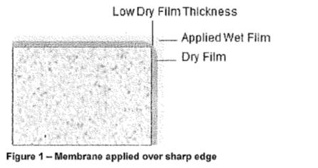
When applied to a sharp edge (Figure 1), a liquid membrane will tend to flow away from the edge as it dries resulting in a low dry film thickness being achieved at the sharp edge. This is typical of any liquid material application.
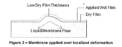
For the same reasons, when a membrane is applied over a localized deformation, be it intrusions or protrusions, the liquid material will tend to flow from the high points during the drying process leaving a film wiht a lower dry film thickness at the peak of the deformation.
Surface Accessibility
Surface to which a liquid membrane is to be applied must be easily accessible to a roller or brush application. This may appear to be an obvious criterion however it is frequently overlooked in the surface preparation.
In the case of off-form concrete the resulting surface frequently has numerous voids commonly called blow holes. These can either be visible voids or voids hidden under a thin cementitious skin which is very weak and unsuitable for a membrane application.
Apart from te fact that these blow holes normally exhibit sharp edges as described above, they also frequently result in inaccessible surfaces wihtin the void.
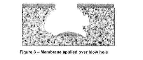
Figure 3 represents the result when a membrane is applied to the surface is that there are significant surfaces within the void that are totally uncoated. This is unavoidable when the interior of the void is not accessible.
Surface Requirements for Membrane Application
In summary therefore, the surface requirements suitable for a membrane application are:-
a. Structurally sound
b. Free of dust an dother contaminants
c. Porous
d. Free from localized surfac defects such as protrusions and intrusions.
While the first two or even 3 of these requirements are considered the waterproofing contractors responsibility, the fourth is frequently considered by the waterproofing contractor as being part of the builder's responsibility to provide a suitable surface.
Concrete Finish in Architectural Building
As outlined previously a building specification normally calls up a concrete finish in accordance with Class 2 of AS3610 for an architectural building.
As3610 is principally concerned with the broadspan surface finish as far as smoothness and levels and less concerned about the localised defects for which it allows a certain tolerance.
AS3610 Class 2 therefore allows a certain denisty of blow holes. Blowholes present a major problem for a successful membrane application as described above so the surface needs to be totally free of these defects for the surface to be suitable for a membrane application.
AS3610 Class 2 also allows for a surface deviation over extended lengths. While the extent of these deviations spread over the extended length presents no probelm for a successful membrane applicaiton, when the extent of the deviation is limited to an isolated area it does become a problem. A fine scrabbled surface may conform to AS3610 but is unsuitable for a membrane application due the numerous peaks within a small localized area.
Responsibilities
Standard constrcution procedure is to specify the concrete finish required in accordance with AS3610.
Waterproofing requirements for concrete finish may exceed the requirements of AS3610.
Adjustments to the concrete surface profile may occur after pouring, such as adjustments to set down areas, resulting in damaged surfaces.
Damage to and contamination of the concrete surface can occur between the Concreting Contractor handover and the waterproofing contractor commencing work.
The following responsibilities are therefore proposed to avoid conflict and unexpected costs being incurred by any party.
Builder Responsibility
- Builder is responsible for nominating the standard of surface finish required from the Concreting Contractor.
- Builder is responsible for nominating a standard of surface finish to be supplied to the waterpoofing contractor at the time of tender.
- Builder is responsible for providing a surface finish in accordance with AS3610 to the waterproofing contractor.
This means the builder is responsible for the costs of remediating and damage resulting from other trades that occurs between the Concreting Contractors hand over and the builder's handover to the wtaerproofing contractor restoring the surface to a standard conforming to the Class of surface nominated under AS3610.
Remediation includes the removal of surface contaminants such as render deposits or other spills and the remediation of surface damage such as step breakouts or surface impact damage.
Concreting Contractor Responsibility - The Concreting Contractor is responsible for handing over a surface finish in accordance with the specified Class under AS3610 to the Builder.
This includes the remediation of any changes to the surface after puring such as set down area adjustments to conform to specified Class under AS3610.
Waterproofing Contractor Responsibility - The Waterproofing Contractor is responsible for all surface remediation necessary to upgrade the surface finish from the specified finish in accordance with AS3610.
The waterproofing contractor should therefore allow in tendering.
- for filling surface defects such as blowholes to the extent permitted the under the relevant clause of AS3610.
- For bevelling or round sharp corners such as steps for set down edges.
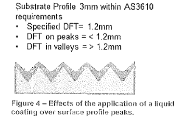
- for either smoothing or applying additional membrane over short distance surface profile deformations allowable under the relevant class of AS3610 to achieve the required dry film thickness over the peaks (Ref Figure 4)
While the above defines where responsibilities lie in the process of achieving a suitable surface finish to the concrete, it does not obviate disputes regarding the assessment of surface in relation to AS3610. This can only be resolved by the appointment of a mediator to which all parties agree to abide.