4.1 The subsill is one of the most important parts of a window. Subsills remove water penetration that drains into it from the window above and moves this water to the outside of the building.
4.2 The subsill acts like a gutter similar to a roof and gutter system. The sill moves “most” surface water entry by shedding if away, but the subsill is the backup which catches, controls and drains the water entry from within the window assembly preventing water entry internally.
4.3 In a cavity constructed window, the subsill is simple – it is formed by a flexible sill flashing UNDER the window frame down to the external skin of façade and expels the water through weepholes.
4.4 In single skin construction, the system relies on a subsill. In simple terms it is like a gutter with and overflow drain (similar to a roof), or a safe tray and overflow drain (used for an air-conditioning unit). The concept is simple – collect the water and remove it to outside the building. As it also forms the connection between the façade and the window that provide a pressure seal to the window installation. It is vital that it is installed correctly and prevents water penetration through the fixing points, at the junctions and at the ends. It is also vital that the sub-frame and window assemble are pressure sealed to prevent water/wind pressure blowing water back through the frame and sub-frame junctions.
4.5 Prior to commencing manufacture or installation on site, obtain from the window manufacturer the sub sill installation details including sub sill damming, joining, sealing and fixing methods.
4.6 These details must be sent to the Team leader for approval. Too often windows are not ordered early enough and compromised subsill details are introduced on site to accommodate delayed windows, but allow also for early completion of render and removal of scaffold. This is out of sequence and creates long term issues with the waterproofing of windows.
4.7 There are a number of parts of a good quality subsill design;
4.7.1 The substrate - Comprising of the formed rebate and waterproofing, or where a rebate is not provided – a flat substrate with waterproofing and a subsill fixing angle (forms a rebate by creating a vertical barrier). The subsill substrate is typically a horizontal surface (such as poured insitu concrete or block work). Following the logic of horizontal surfaces being the lowest point where water can “fall” via gravity the sill is therefore prone to water ponding/ingress, the surface is waterproofed. The surfaces are typically designed to catch and control any water entry by draining the water to the outside upstream to downstream of the window assembly. The waterproof substrate is a secondary catch and control system as regularly the primary system is compromised usually in a minor manner, however if the sill is not waterproofed then water will run or track into the building.
4.7.2 The extruded subsill – a purpose designed channel and rebate to accept a window assembly above it (from a structural connection perspective), with drainage slots (forming “overflows”) and fixed directly to the substrate through the top with fixings sealed (as below). This forms the “gutter” or primary drainage system for the window assembly.
4.7.3 Dam angles – these are essential to close in the ends of the subsill to create a “dam” – they are effectively the ends of the “gutter” below the window. These prevent the water flowing off the end of the sill/gutter and internal of the building.
4.8 It is important that a vertical barrier is formed under the subsill to prevent a flat direct path for water to be driven into the building. It’s a bit like a turn up on a roof sheet. This can be as a cast rebate, or a waterproof angle on a flat surface. This provides an off set for the driven water to be directed to the lowest and least point of resistance which is the outside of the building.
4.9 The decision to use a subsill is fundamentally simple. It is application of use/risk and window pressures. Domestic windows are not designed with a subsill – but they are designed for one or two storey houses with lower wind pressures with a cavity design - so any water that blows past the window, drains out. A commercial window is designed for more substantial structures and much higher wind pressures and because they are typically in a single skin construction, they require a subsill to drain.
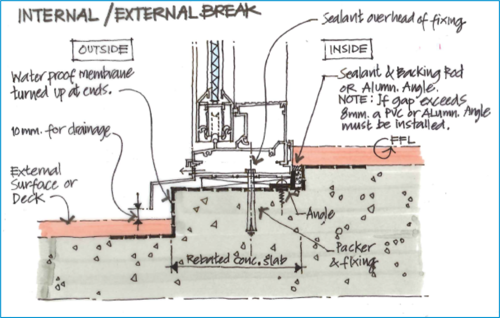
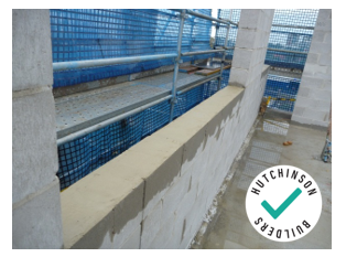
Above – single skin Subsill design – this is ideal for all areas
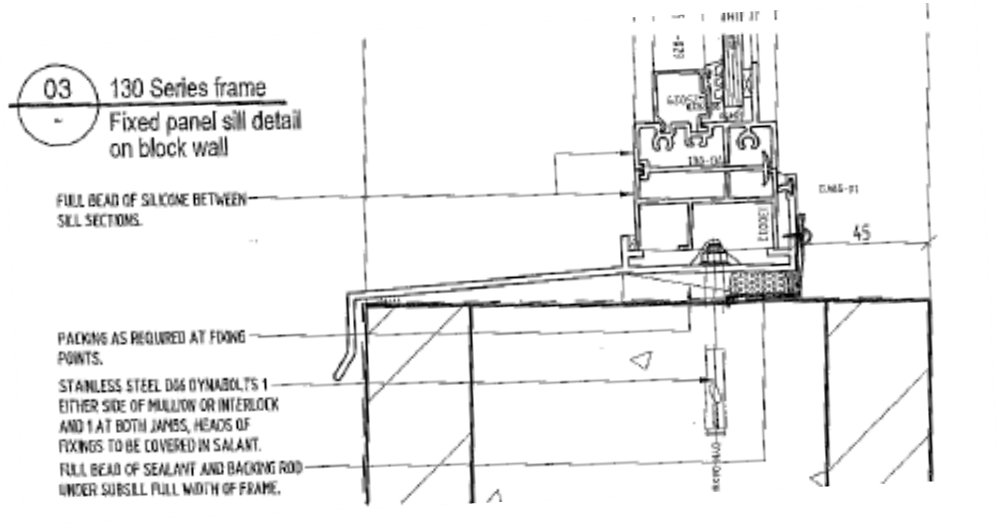
Above – single skin Subsill design for block windows – top the block work, waterproof membrane, angle fix rebate, then fix subsill
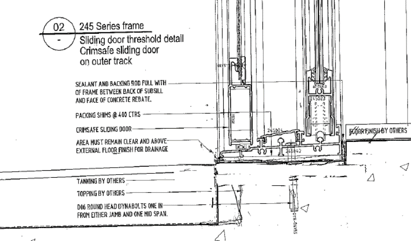
4.10 In the event a domestic section is used in a single skin application, and no subsill is available – noting this is a VERY UNDESIREABLE, the design and installation must be approved for use by the team leader. The detail is as below – noting the importance of the external floor finishes – they MUST be lower than the rebate/sill under the window. The bottom of the rebate must be able to freely drain an all times and points of the opening.
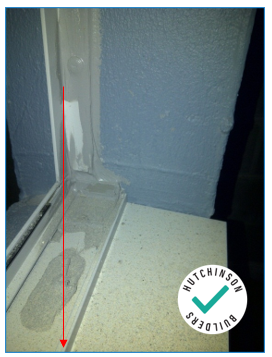
4.11 Essentially driven water/water ingress enters the building, hits a vertical barrier, and stops the water from progressing any further. The water then runs back out of the building. The internal external break must be water tested on site prior to commencing window installation. It is surprising how many fail.
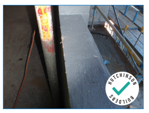
Above - Formed Concrete Rebate for Aluminium Sliding Door Suite Water Proofed.
Above - Aluminium Angle to Form Vertical Angle
4.12 The water stop angle provided as the vertical barrier must extend from the structure and seal onto the subsill note that polyurethane sealant cannot exceed 8mm.
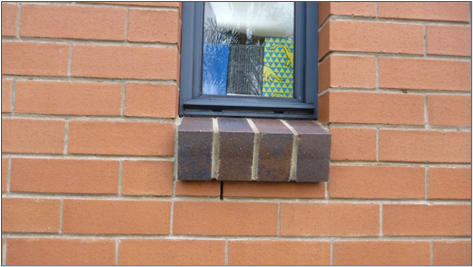
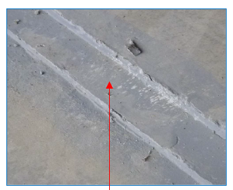
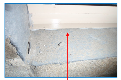
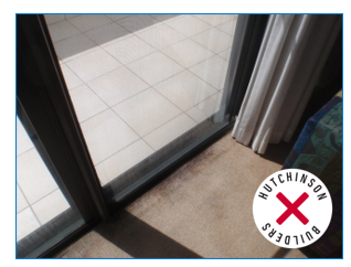
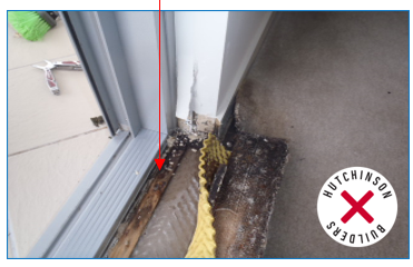
4.13 This provides and internal/external break. Failure to provide this allows water to immediately affect internal finishes such as floor coverings and timber studwork. Examples of this failure are shown below.
4.14 A formed rebate/set down also allows a door sill threshold section to be flush with the internal finishes of a building. This should be developed early in the project to ensure correct rebate sizes are formed – it is a UNNECESSARY cost to rectify these due to poor planning or complacent supervision of the structural trades during construction.
4.15 Prior to the installation of the approved sub sill sections the rebate or reveal it must be waterproofed to prevent capillary action allowing water a path into the building through a porous masonry structure. Refer to the Waterproofing Policy in these applications. Reference should also be undertaken to AS4654.2 and AS2047.
4.16 Beingin by topping the surface to meet the required finish for waterproofing. To using an approved high strength levelling compound for the substrate preparation. The substrate should fall towards the outside of the building.
4.17 The waterproofing membrane selected MUST be compatible with the window polyurethane sealant. Ensure that written evidence of compatibility has been provided by the membrane manufacturer and the window installer prior to installation.
4.18 This compatibility extends to the render in rendered applications (Refer Render Manual) and becomes a three way compatibility that must been documented to ensure the warranty is preserved. The window must be fully installed prior to the application of any render work on the outside. Render must not bridge between the waterproofed substrate (wall opening) and the window frame or sub frame. Additionally AS2047 requires that a bond breaker be installed between the render and window frame. Windows must not be in contact with the rendered surfaces or impact coatings. The junction between the all metal or timber components and the render must be “V”ed and flexibly sealed prior to painting.
4.19 The subsill is measured ONSITE and cut in a single length and installed. The subsill must extend the FULL width of the opening and be installed with a maximum 3mm clearance to the structure.
4.20 Where windows are joined at a corner, or are longer than a single 6.5m maximum length of subsill (shop fronts etc – see photo), then the subsill must be joined with a mechanical junction – meaning it is backed with an aluminium profile and screwed or riveted together
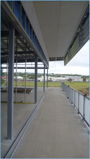
Simply butting two Subsills together and sealing between them is UNACCEPTABALE and non-compliant. You would not allow this sort of workmanship or detailing on a gutter for a roof, and it is not acceptable in window installations.
4.21 The Subsills should be joined with joiner subsill section which is sealed between the subsill and joiner and then mechanical fixed, then the butt junction of the two Subsills sealed using the joiner as a backing plate. Procure manufacturer details PRIOR to installation.
4.22 The subsill MUST be adequately supported along its length and to prevent the fixings pulling the subsill out of shape/bending it down (creating ponding like and overdrive roofing screw) there myst be a packer under every subsill fixing.
4.23 Waterproofed windows and door openings will not be drilled and plugged without use of chemical anchors. Alternatively, openings can be pre-drilled and sealed with Polyurethane prior to anchor installation. Anchors will be installed immediately after Polyurethane application. All predrill holes must be vacuumed or air pressure cleaned prior to the installation of the Polyurethane sealant. Sealant must push out around all sides of the fixing on installation of the fixing to allow the sealant to for a continual seal between the fixing and the waterproofed substrate.
4.24 Seal the sill against the jamb structure and seal OVER the heads of the subsill fixings.
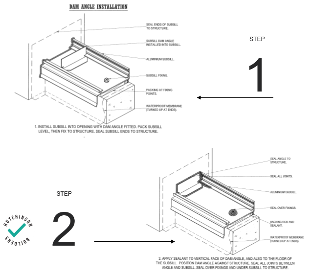
4.25 Next install the Dam angles. Physical PVC or Aluminium dam angles are mandatory and no matter what the installer states they are NOT optional. Sealant only on the ends of the subsill will not be accepted as a method of damming the subsill. Refer to the below example. All dam ends must have an aluminium or PVC angle installed to prevent water entering the building around the sub sill as below.
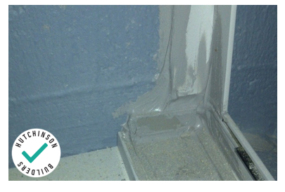
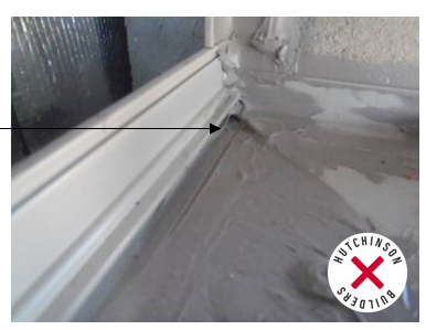
Incorrect Installations
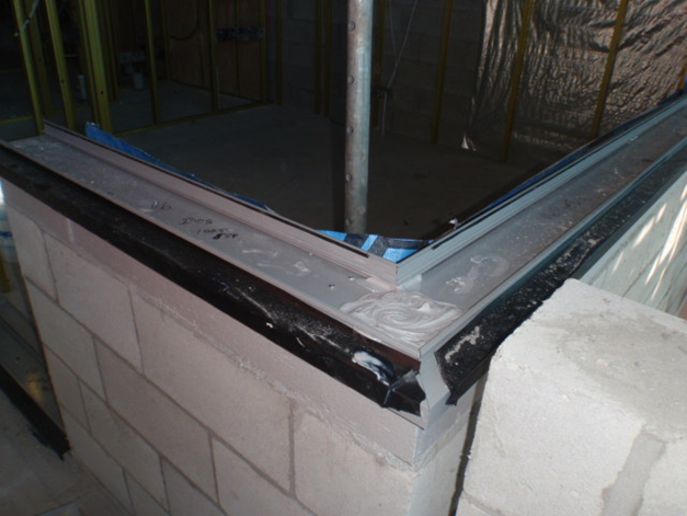
Above - the dam angle must be sealed completely across the subsill profile including under the window support leg In this case the sealant is NOT correctly applied
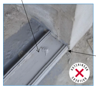
Above - Structure gap should be within 10mm prior to water proofing and no Dam Angle Installed, completely unacceptable subsill install.
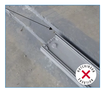
Above - Sealant attempted to be used as a Dam Angle
4.26 DON’T snap off the downturn leg of a subsill. Subsills are not extruded with this leg for fun. It has a purpose – to protect the rebate cavity under the sill from driving rain in high pressure applications. Removing this reduces the weatherproofing of the window considerably. Where a level or minimal step, a threshold is required – use a purpose designed threshold ramp (refer Raven etc). Note AS4654.2 provide detail on minimum vertical height for subsill and water stop angle rebates.
4.27 Make sure the subsill drainage slots are free draining. They may be affected by render droppings. Tilers may incorrectly bed or design levels may be incorrect resulting in tilers or concreters installing floor finishes OVER or up to weepholes.
4.28 Render and external finishes will be kept 15mm clear of any sub sill base or weepholes to allow for free drainage unless approved by the Manufacturer of the window or Team leader.
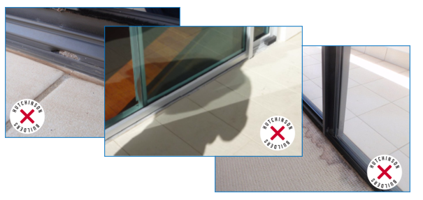
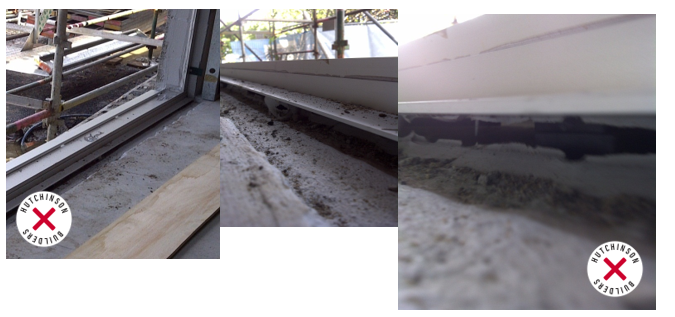
Above - Failure to keep Subsills free-draining results in the water having nowhere else to go than internally.
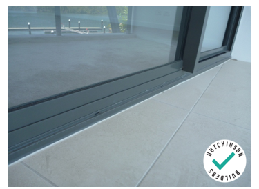
Above - Proper detailing with tiles below subsill - drainage slots well clear.