- 4 Minutes to read
- Print
- PDF
6. Handrails
- 4 Minutes to read
- Print
- PDF
6.1 Refer BCA volume 1 D2.16/D2.17 and BCA Volume 2 (domestic Class 1) part 3.9.2 prescribed handrails
6.2 See also External waterproofing area policy
6.3 Handrails are 865mm min for stairs and 1000mm min for all other areas. Measure this from the TOP of a hob as a precaution, account for expected floor finishes and to be sure set handrails at 900mm for stairs and 1050mm elsewhere for landings/balustrades. There is little issue with having handrails slightly higher than the MINIMUM. Being 1mm too short makes the rails grossly defective and unsafe and defective under the BCA.
6.4 Balustrades are to be spaced at 125mm maximum centres and must never contain gaps exceeding 125mm.
6.5 Balustrade may incorporate horizontal balusters for handrails used where the fall from the FLOOR height to the surface below is less than 4m. If the fall is 4m or greater, then there can be NO elements between 150mm from the floor to 760mm from the floor that facilitates climbing.
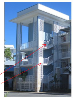
Above – horizontal batten screens with non-climbing sections at the handrails – additional battens used with 5mm between battens at stop climbing of the battens. Other handrails using vertical balusters only
6.6 Wire balustrades have a high initial failure rate and a disastrous long term compliance failure rate – it is strongly recommended these are NOT installed. Where they are required to be installed notwithstanding every possible protest, ensure a clear written instruction to install these is provided AND the maintenance manuals advise the building owner of the need to test for compliance regularly and adjust wire tension to ensure compliance. Wire balustrades must only be used with approval of the design by the Team leader.
6.7 Balustrades must be engineered for the anticipated load – domestic applications require a different load to a retail void or stadium barrier handrail/balustrade that might have dozens of people against it - the standard for design is AS1170.2 – and this provides different handrail and infill loads and Glass balustrade infill design requires that a handrail to remain in place as fall protection even if a glass panel is broken and that glass infill’s be designed to AS1288 to meet the loads determined by AS1170.2. (see below).
There are several options for this such as those noted in AS1288.
"Interlinking handrail. The handrail is non-load-supporting, unless a panel breakage occurs, and is connected to adjacent panels of glass, or the building, where the adjacent panels are at least 1000mm wide and three or more panels of glass form balustrade. If any one panel fails, then the remaining panels and handrail shall be capable of resisting the load defines in Clause 7.2.1 and 7.2.2"

6.8 The glass selection is also important – toughened, laminated, laminated heat strengthened are options – each with pro’s and con’s for safety, edge delamination etc for consideration by the designer - make sure the CERTIFIER and BUILDING owner are a part of the design process to ensure the correct balustrade type is selected to meet the Code and for the intended use/application
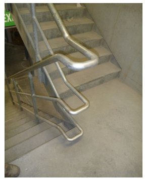
6.9 Stairs design is critical to the construction of good handrails. Many designs will locate the first riser at the landing level, but this affects the continuous handrail junction at the landing as there is a full riser difference in the heights of the rail – when you get the “near vertical” transition of handrail from one flight to another. This provides for a rectangle landing.
6.10 Where the stairs are designed with the first riser set ONE tread back from the adjacent flight (like the “L shaped landing” as below extract from AS 1428.1), the handrails connect directly into each other at the same height. Note the handrail in a disabled stair must extend past the point of the last riser as per the below diagram.
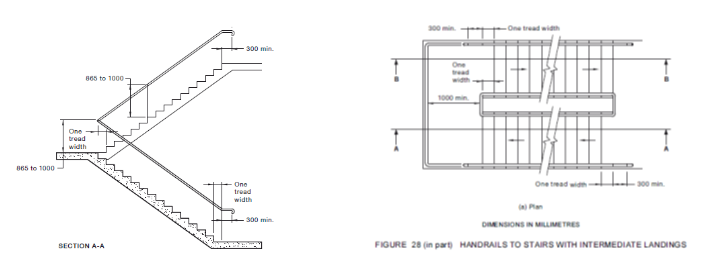
Below left – first upper flight riser and first lower flight riser align – meaning the handrail align differently by one tread – meaning the handrail has to “kink up” to work as a continuous rail – or extend a tread size into the landing as it has in the photo with a flat section to achieve a common height for connection. Where the handrail is not continuous – “squeezing” the stairs into this arrangement saves space. Otherwise it is a messy way of achieving the same size. It is difficult to achieve a good finish to the vertical face of the gap between the stairs as well – because there is no “termination” point – no stringer.
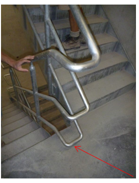
Above - Where the first riser on the upper and last riser on the lower flights is flush, the gap on the landing between is difficult to finish as there is no stringer on the lower flight to finish to.
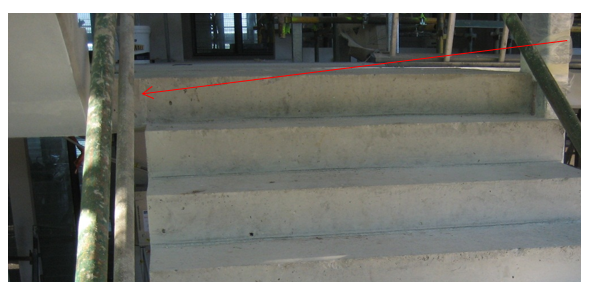
Above - Lower flight begins one tread past the first riser of the upper flight – meaning the handrails are aligned at the upper flight riser – and therefore does not need to extend into the landing finish between the stairs fit between the stringers – This makes for a neater applied finish.
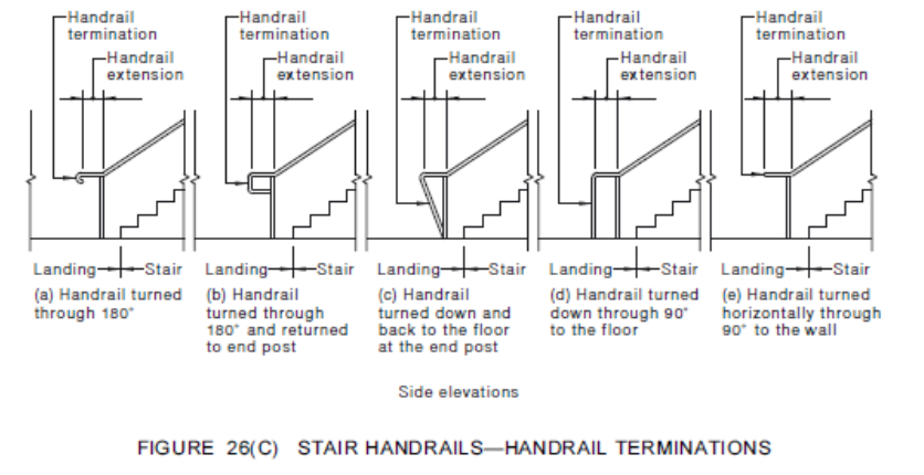
6.11 Handrails are continuous (welded together etc) for all stairs except fire stairs and domestic stairs (which are not “required” to be. Handrail terminations may be a simple end cap for fire stairs and domestic stairs, and for disabled compliance buildings the termination are as per AS 1428.1 diagrams (below).
