Detailed drawings should be provided that includes information on the following areas:
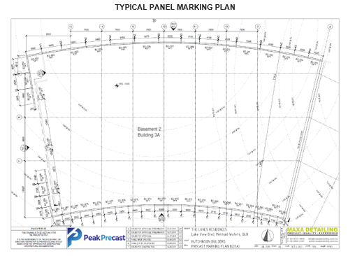
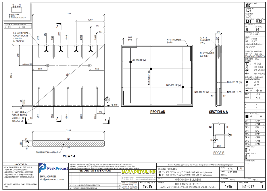
• Marking plan of panel locations
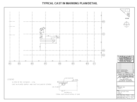
• Marking plan of cast in connections
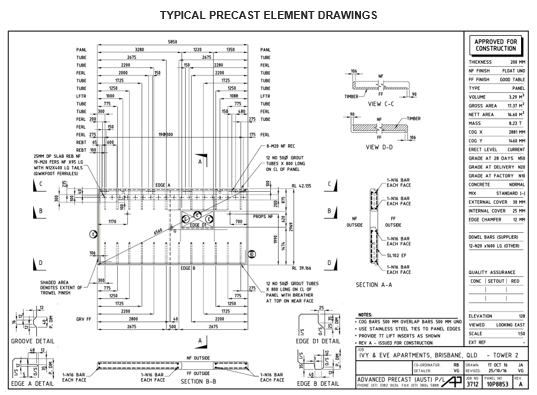
• Design of the panel itself for the in-situ application as part of the final structure, ensure suitable construction tolerances are incorporated into the design for the works.
• Design of the panel for lifting and other installation loads.
• Design and location of footings and slab for the building or structure.
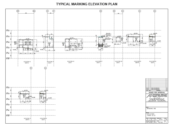
• Layout of the panels during construction of the building or structure with temporary bracing installed.
• Layout of the building or structure in its completed form with temporary bracing removed and permanent connections detailed.
• Design review of pockets/recesses/rebates in panels and slabs for recessing structural plates to provide for floor finishes/fire rated applications for architectural finishes and certification. Ensure engineering design accommodates these differences.
• Review architectural drawing vs structural drawing/shop drawing for ship lap details where applicable – have engineer confirm edge bursting reo/extent of grout required for the works
• (NOTE: for panels with a ship-lap connection the grout is typically only approx. 75% of the total panel thickness as the ship-lap isn’t grouted)
The builder and/or panel erector will often determine how many groups of drawings are to be provided for the project. However, all of the information above should be clearly shown on the drawings and is to be checked by a suitably qualified engineer.