For the purposes of this topic ‘Precast Concrete - Vertical Structures’ the information is limited to walls and columns as a part of the building structure. It doesn’t cover precast concrete pipes/culverts, precast floors and beams or the like which although in many ways are similar and use similar controls, but we have separated these as they have fundamentally different purposes and therefore considerations.
In respect to Tilt-up Precast Concrete Structures, the quality controls are very similar – but the works are site cast. There are separate ITP’s, SWMS and Checklists for these, but the principles remain the same.
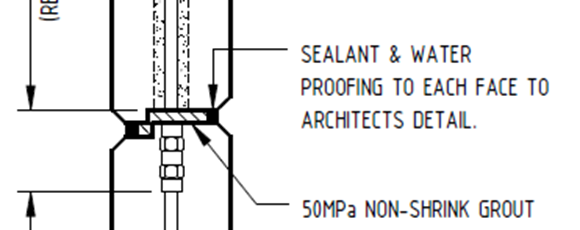
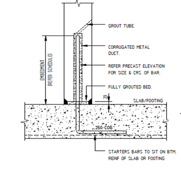
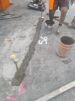
Building good structures including all facets of precast concrete is critical. The fire rating and structural soundness of all aspects need to be as scrutinized as if it were the insitu slab the precast is supported by. The grout requires as much focus as a slab – and given its site mixed, and hand compacted, strict controls are required to ensure this is correctly constructed to meet the engineering design.
There are essentially 5 applications of ‘Precast Concrete - Vertical Structures’ to consider;
External (façade) load bearing elements
• In this application, the building is supported BY THESE precast elements. The slabs will be connected to these and the load transfers from the slabs into and down the panels to the foundations
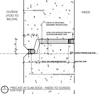
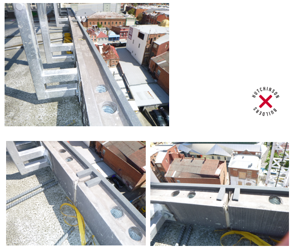
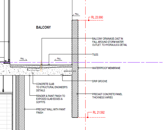
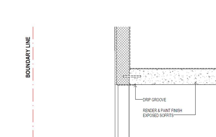
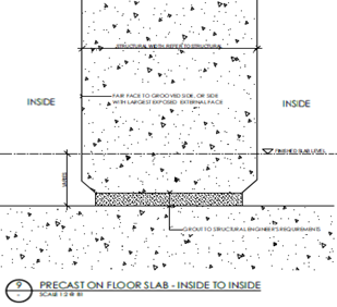
• Usually constructed with a ship-lap detail to provide weatherproofing to the external (the ship-lap creates a vertical waterstop like a rebate as we would for any other external wall as good building practice) – see examples below – the ship-lap detail is usually on the outside face and allowed the free drain, however it may be on the inside face. This detail is directly linked to the ability to access the area for grouting
• It’s not uncommon for the detailing from Architect to structural drawings differ (which requires early resolution) – in this case the rear fillet and extent of grout – two very important aspects structurally

Above: Grouting access from both sides required to right.
Above: Grounting access from outside only.
Grouting access from inside only below (ship-lap has compressible filler to prevent grout loss where no access on outside face)
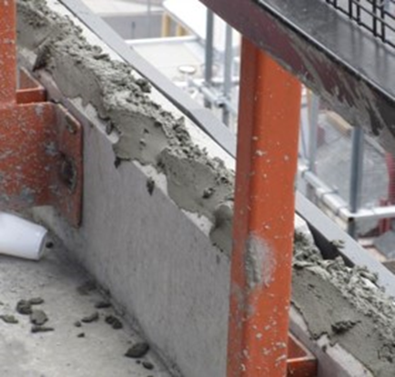
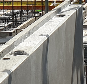
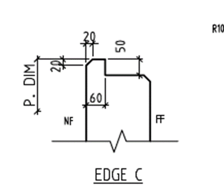
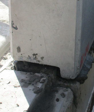
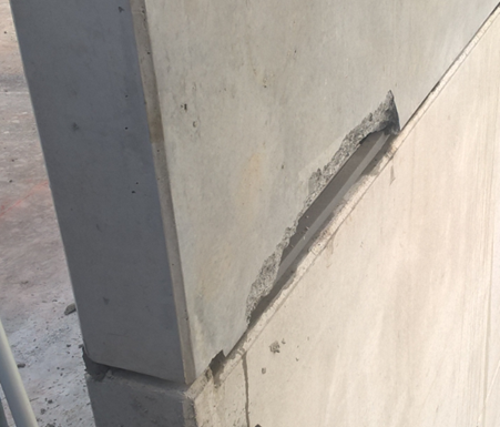
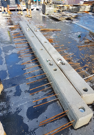
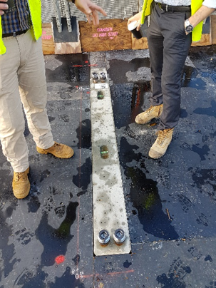
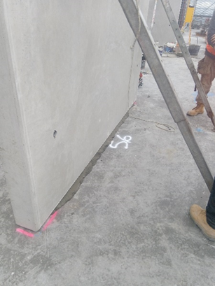
• The dimensioning of the ship-lap is important structurally if the ship-lap isn’t grouted – the ship-lap usually needs to be as small as possible (usually min. 50mm wide) to provide the maximum grouting area which requires careful handling when installation occurs. There is risk of damage to the small unreinforced area (see example below)
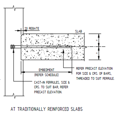
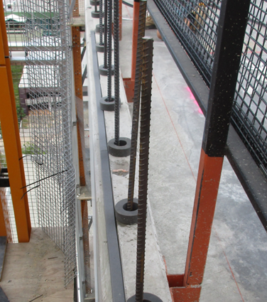
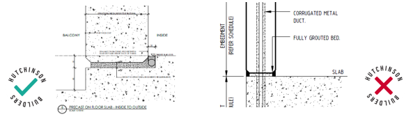
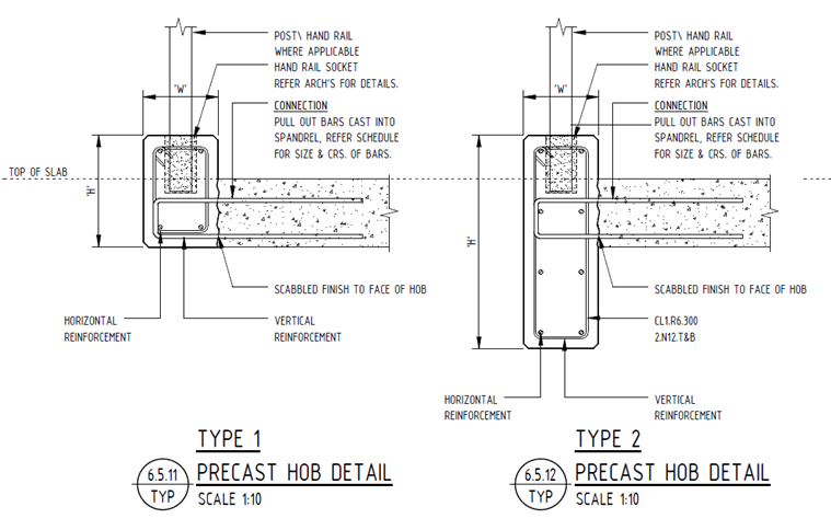
• The base of the walls where the load is highest (the greatest amount of weight from above is transferred) onto this area which is usually set in a rebate (no shiplap). This detail increases the loadbearing area available (increased width)
• It’s not uncommon for the detailing from Architect to structural drawings differ (which requires early resolution) – in this case below the rebate is missing on the structural drawing
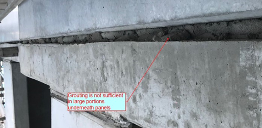
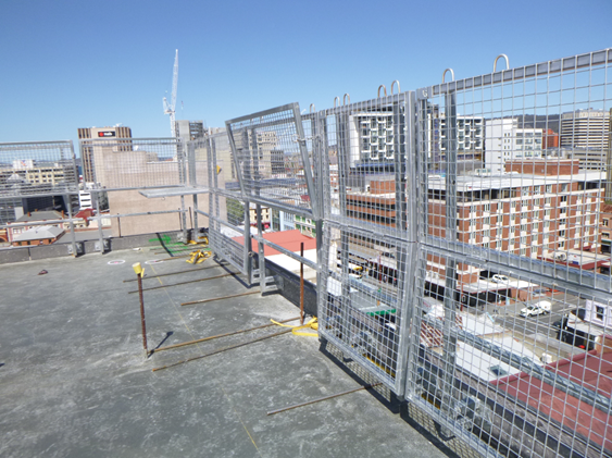
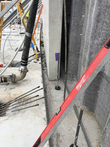
In the below case, the ship-lap has been constructed so that the ship-lap is on the internal side – preventing access to compact the grout/ verify grout depth from the inside face. Because the building isn’t scaffolded the only way to check the grout is abseil over and drill without the engineer inspection. Drilling form the inside would compromise the waterstop detail. Is also more difficult to adjust the panel and requires any panels height/location adjustments to be completed placing force on the thin unreinforced ship-lap waterstop section (using a panel lever/pry bar) which is not ideal.
External (façade) non-load bearing elements
• For this application, the building structure is supporting the precast elements
• A ship-lap detail maybe used to provide weatherproofing to the external depending on the design – see examples above, but pending the detailing, a flat precast connection may be adopted where weatherproofing is not a requirement (example below)
• Non loadbearing panels are usually provided where a wall is required to be fire rated but may not have structure under it to provide support so the Precast element is ‘hung’ off the building structure – includes fire separation spandrel and parapet walls, walls with in the fire separation zone (such as zero boundary construction) and the like.
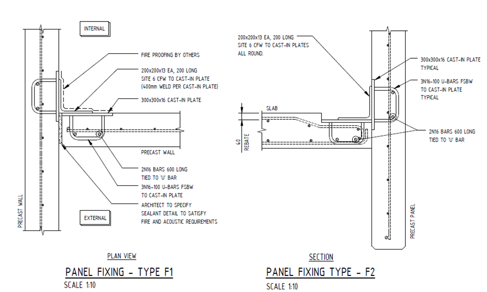
• The connections may be a welded or bolted brackets/plates for retro fitting of the panel after the structure or cast in where the precast is temporarily propped (both examples below)
• It’s not uncommon for the detailing from Architect to structural drawings differ (which requires early resolution) – in this case below the welded bracket may require consideration to recessing for applied wall and floor finishes and fire rating of the connections and has been shown with a conflicting detail to the structural drawings
Internal load bearing elements - walls/columns
• In this application the precast element is part of the supporting structure.
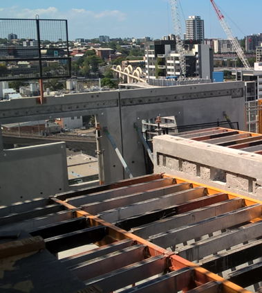
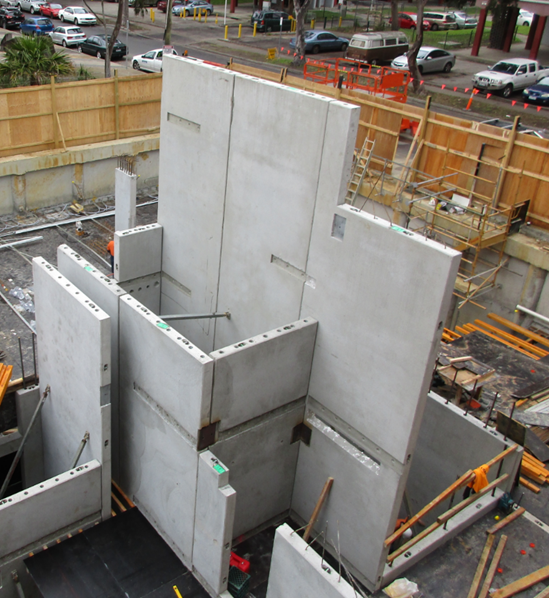
• Loading bearing walls may be subjected to shear reactions structurally (such as the shear lift core below) and require additional connections to achieve the engineered solution requirements
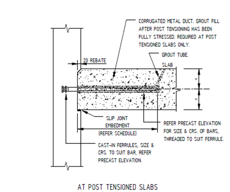
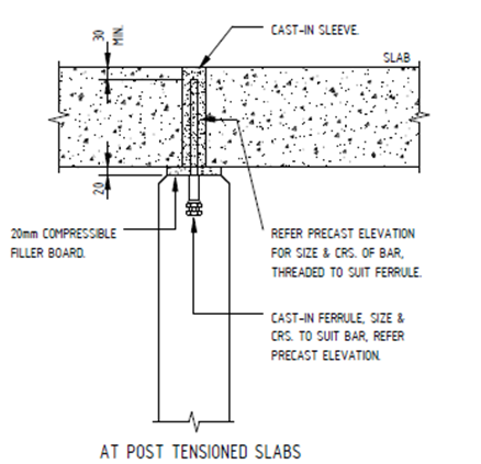
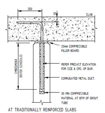
• The element is a solid connection at top and bottom. Post tension slabs differ to traditional reinforced connections as they have a movement joint for the post tensioning process then the element is grouted to a solid joint
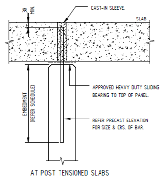
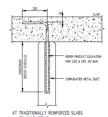
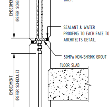
Above - Typical Head Details
Above - Typical head with formwork in place
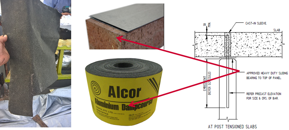
• Slip joints are usually 2 layers Alcor or proprietary galvanised or stainless sheets with grease between them
• Grouting access from both sides typical to the base
Internal non-loadbearing elements
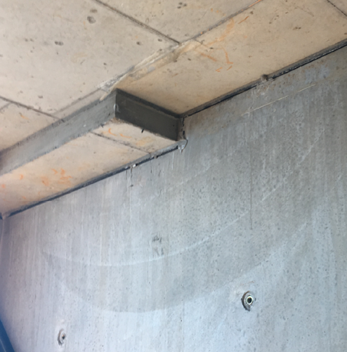
• In this application the precast elements may form a fire barrier for example between compartments but are not load bearing so require a restraint at the head but a gap between he structure above and the top of the precast element to permit deflection of the structure above.
• Base connections are typically fully grouted fire resistance (refer Internal loadbearing elements details above)
Retaining walls
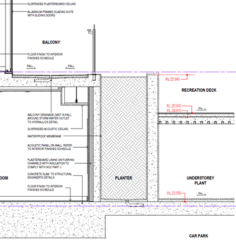
• This is where the Precast elements retain soil/hydrostatic pressure/other structures in the form of basement perimeter walls (fully or partially underground), planter boxes and landscaping retaining walls
• These structures take different loads to other elements mentioned above and have different water proofing requirements.
• They may be constructed against other temporary structures such as shoring walls and have limited access to one face of the precast element (requiring specific construction methods)
• They may be constructed in corrosive conditions that require different grades of concrete/reinforcement cover to resist attack by salt / brackish water or other chemicals/contaminants
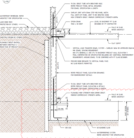
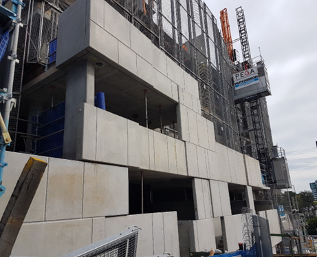
• A precast element may be a combination of several of these applications as well and require consideration across many aspects – example below - Planter, load bearing, façade panel with visible surfaces