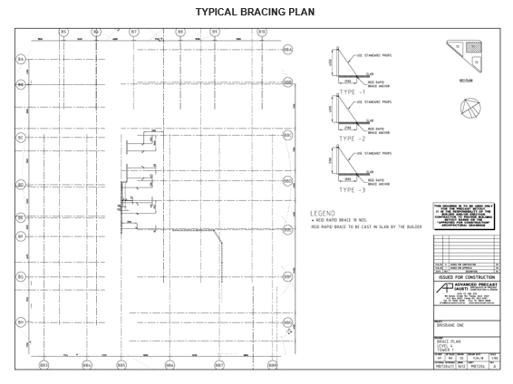
Drawings for the erection of the panels should include details on how the panels are to be placed and secured into position. Information to be shown on these drawings include:
• project location
• date and issue number of the drawing
• position of brace connection points on the panel and the ground
• brace specifications and/or required capacities
• levelling pad details
• relative locations of panels
• details for brace footings including dimensions, location, anchor type, and concrete strength at time of erection, or where no footing provided - minimum strength or permanent structure were used to prop the works and
• details on knee and lateral bracing (if applicable).
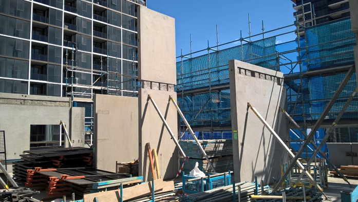
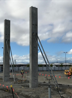
Determine precast erection procedure/sequence with engineer prior to commencement.
It must be clear as to when temporary supports and temporary bracing/propping can be removed.
Incorporate this sequence/document into the ITP, SWMS and Pre-cast Concrete Installation checklist (high risk activity preplanning checklist).
Verify structural connections through welding tests or similar testing as a part of this process
Engineering certification must be provided with the erection drawings for the design of the temporary supports/props prior to installation.